3D Modeling
Skip to:
[Knight Chess Piece][Laser Cut Box with Lid]
[Other 3D Models Done]
Knight Chess Piece
Requirements
- Base: 30mm
- Height: 50mm
- Head Thickness: 5mm
- Hollow Base
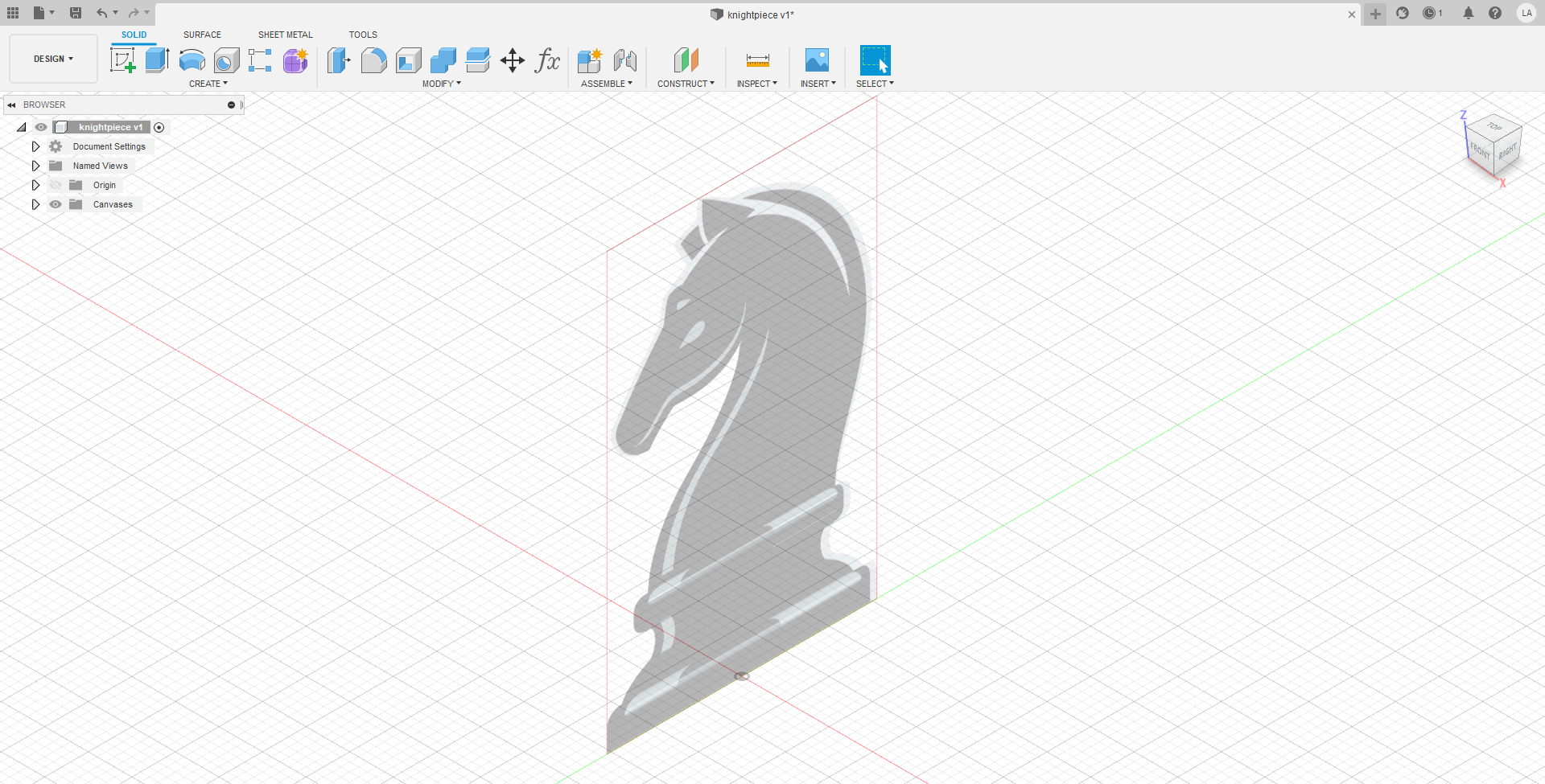
First, a [reference image] was chosen off of google images. The image was inserted as a canvas to serve as a reference when I was modelling. The canvas image was set to a height of 50mm, fulfilling the height requirement. Disclaimer, as this task requires copying certain features off an image and many curves, it will be impossible to dimension and constrain every sketch.
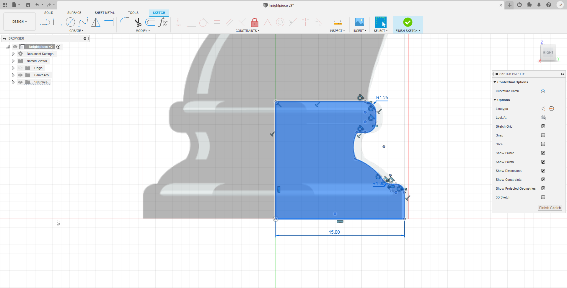
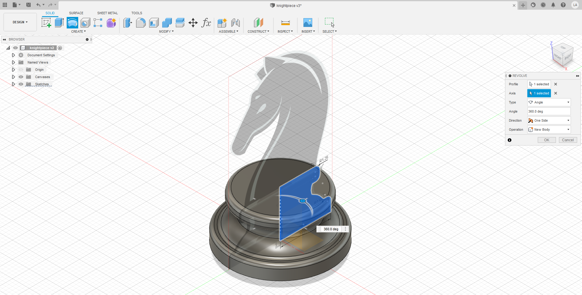
Next, the sketch for the base was drawn. As the revolve tool was being used, I only drew one side of the base. The base was drawn using the line tool, fillet tool for the rounded corners and the 3-point arc tool was used for the curved parts The base was dimensioned to 30mm in diameter in this step. After the sketch was done, I revolved it around the Z axis by 360 degrees to get a full base.
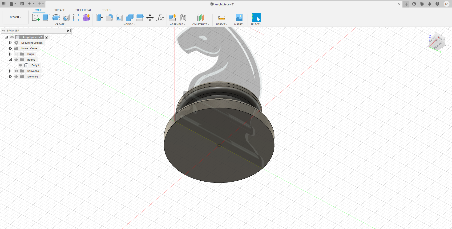
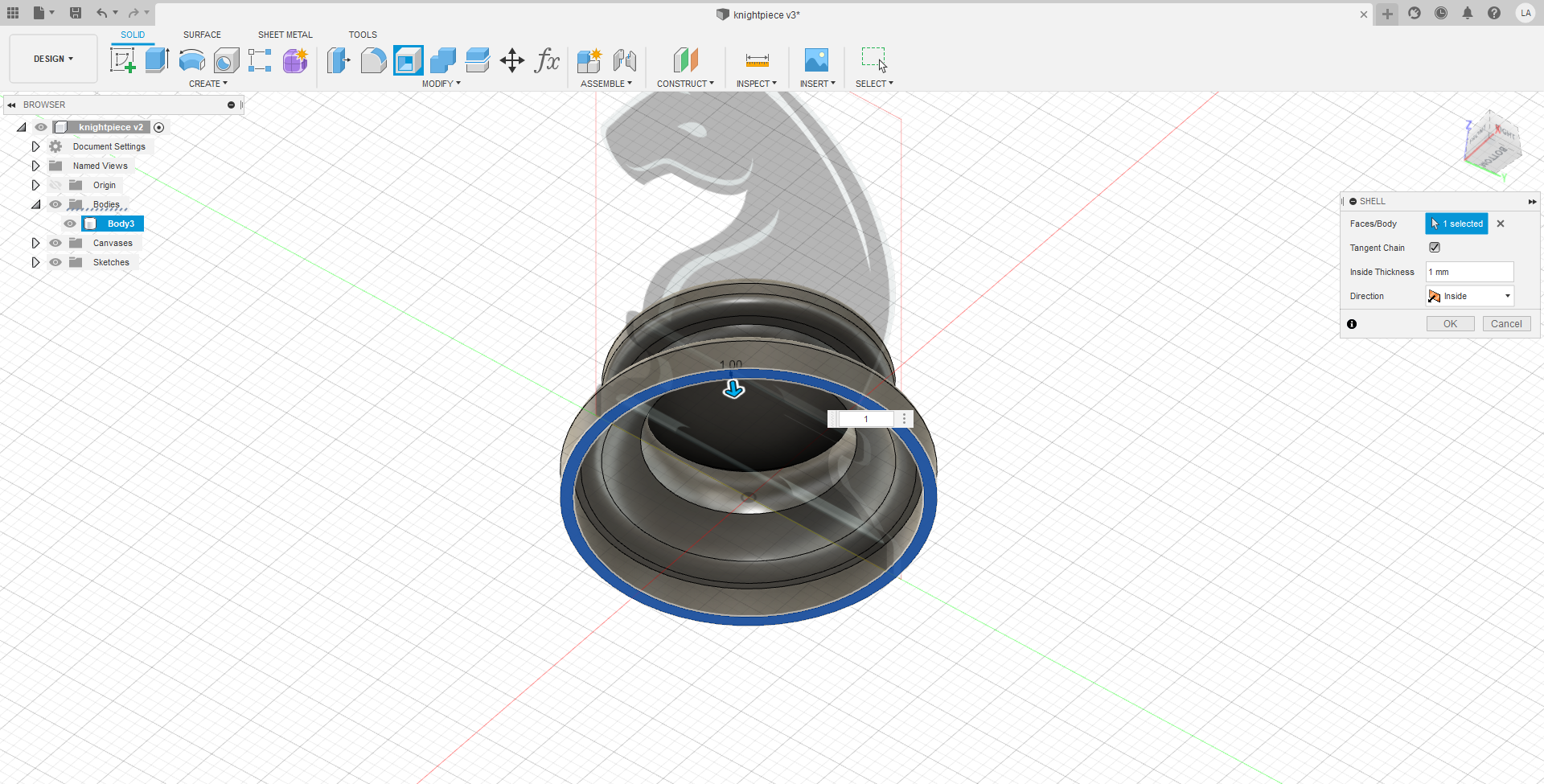
Next was hollowing out the base. To do this, the shell tool was used, and a wall thickness of 1mm was chosen arbitrarily
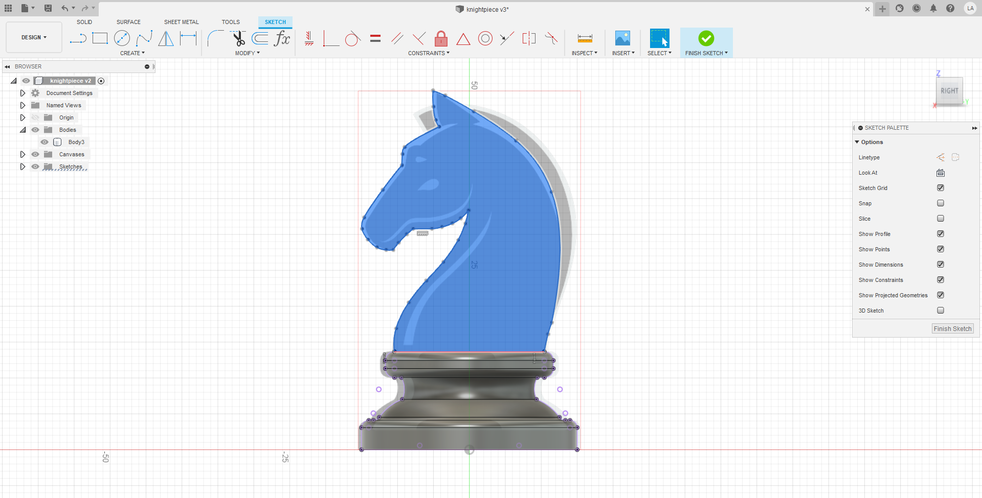
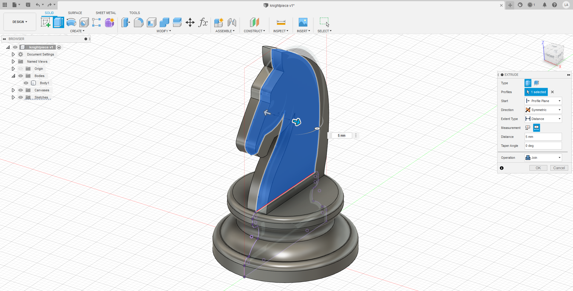
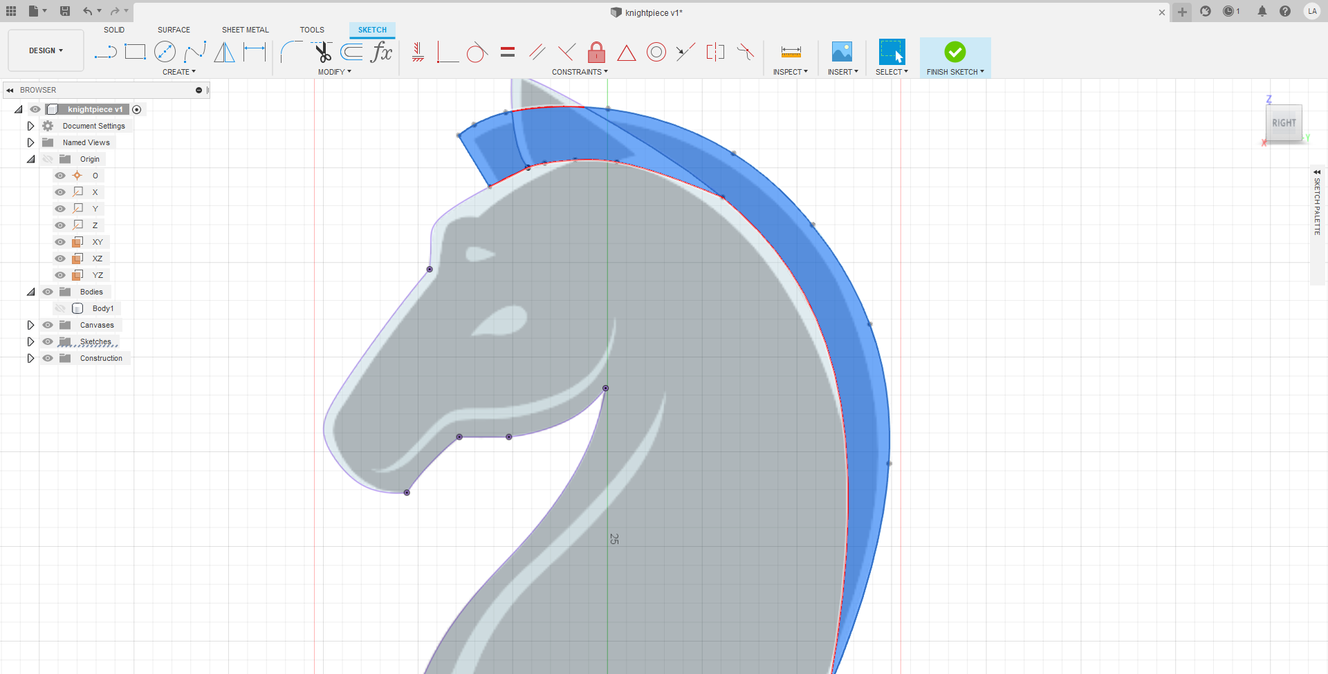
Moving onto the main head of the knight piece. As the head is entirely made of long, continuous curves, the spline tool was used to draw the sketch. I wanted the mane of the horse to be of different thickness, so for this step the mane was ignored during the sketch. The base was projected so that the sketch can anchor to points on the base. The sketch was then extruded symmetrically to a total width of 5mm, fulfilling the requirement for head thickness. The extrusion was joined to the base.
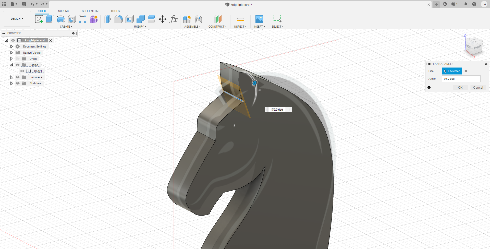
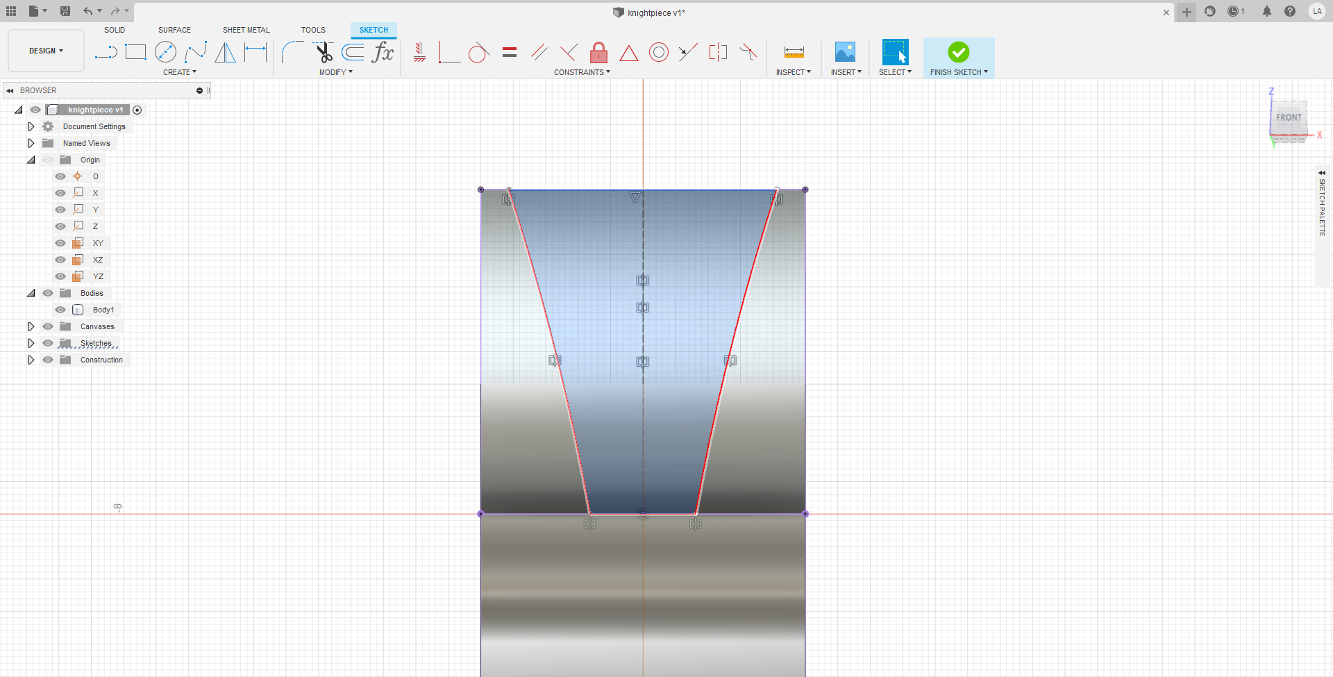
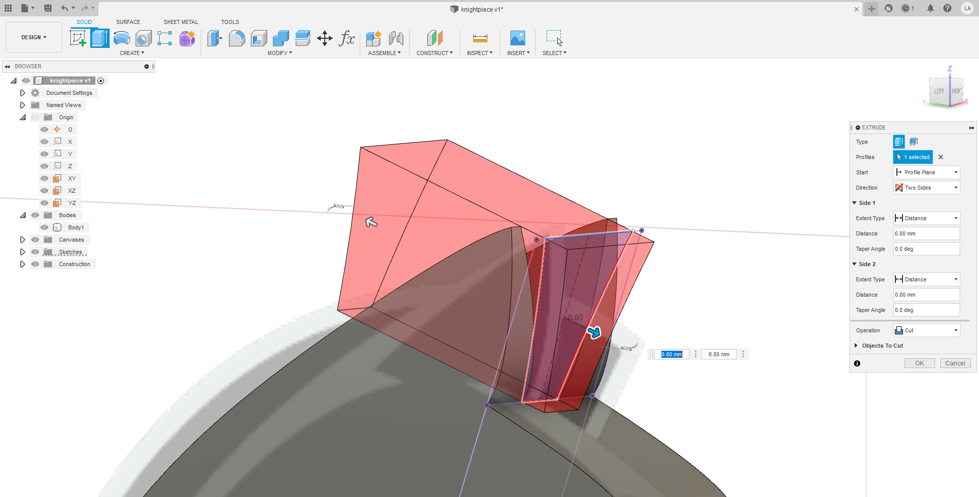
Afterwards, in order to make the ears, I first added a plane using the plane at angle tool. I tried my best to make the plane tangential to the ear curve. Afterwards, the basic sketch for the gap between the ears was constructed, then cut outwards on both sides in order to make the ear shape.
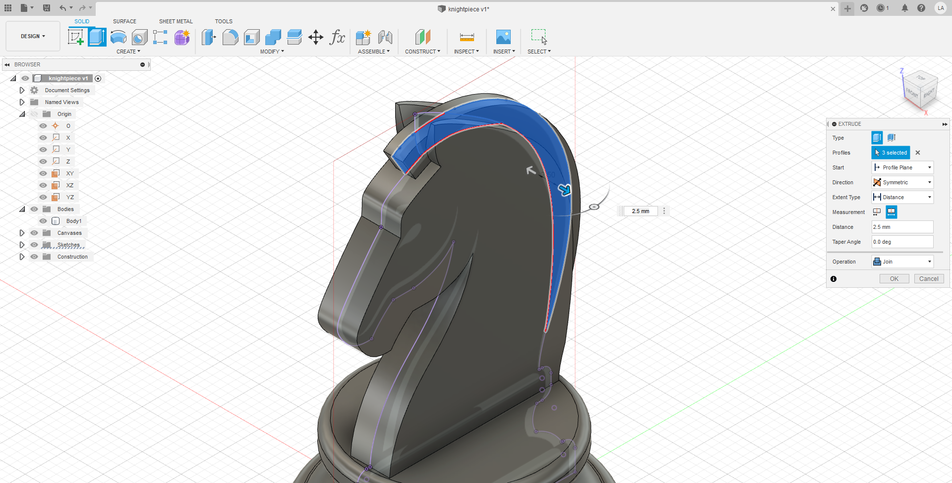
Onto the mane. The head was projected such that the sketch for the mane can anchor to points on the head. To get one long continuous curve, the spline tool was used throughout the whole sketch. The sketch was then extruded to half the head's thickness, which is 2.5mm.
Finally, to knock off the hard 90 degree angles on the head, the chamfer tool was used on majority of the edges.
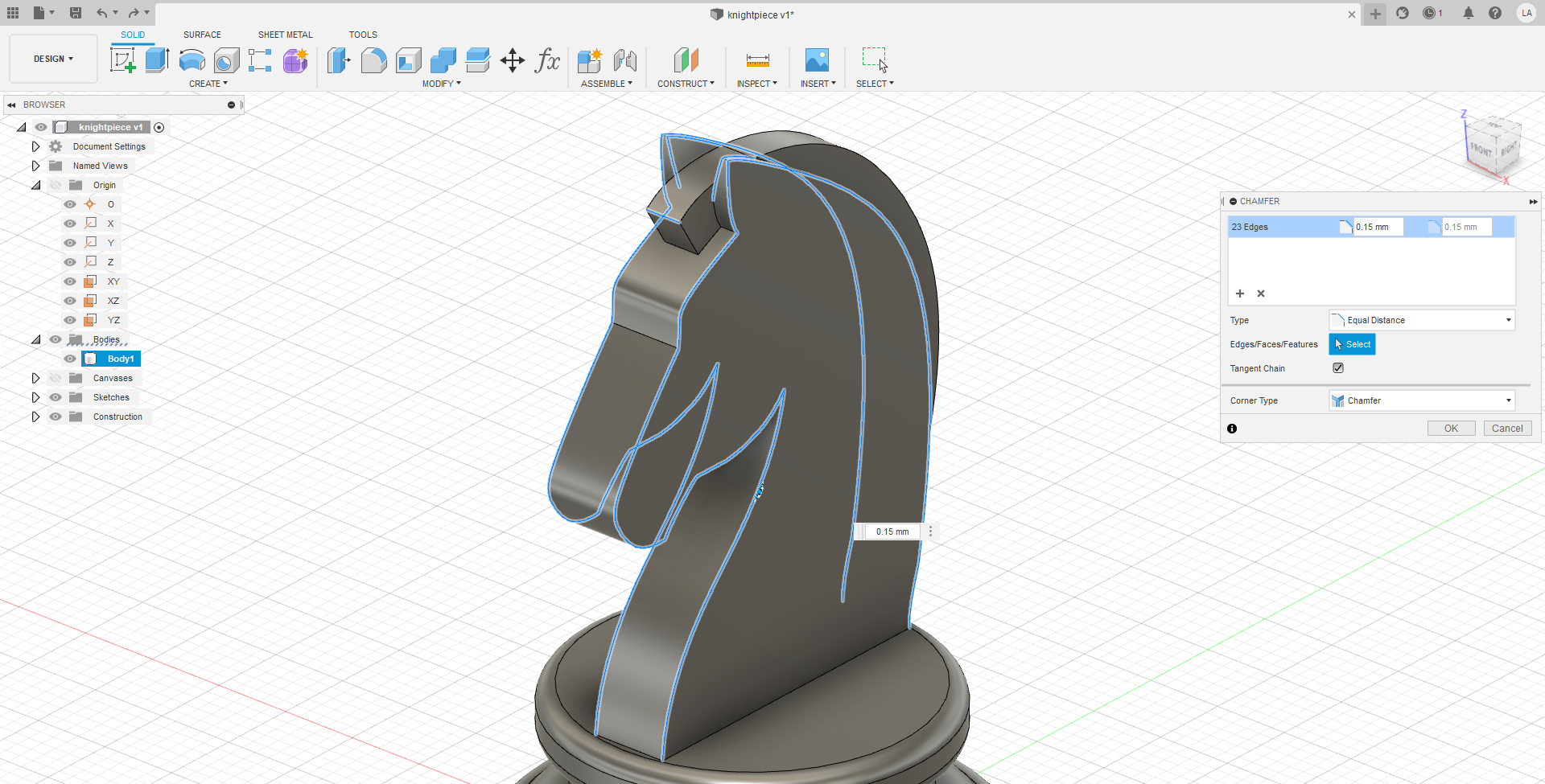
And with that, the model is done, below is the embedded 3D model.
Modelling a Laser Cut Box with Lid
First a sketch was done to make sure that I have a plan.
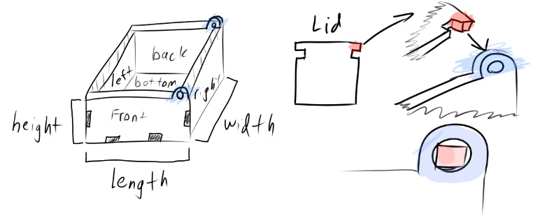
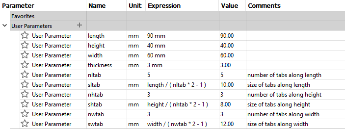
Next, parameters were set in the program.
Making a basic box without the lid first.
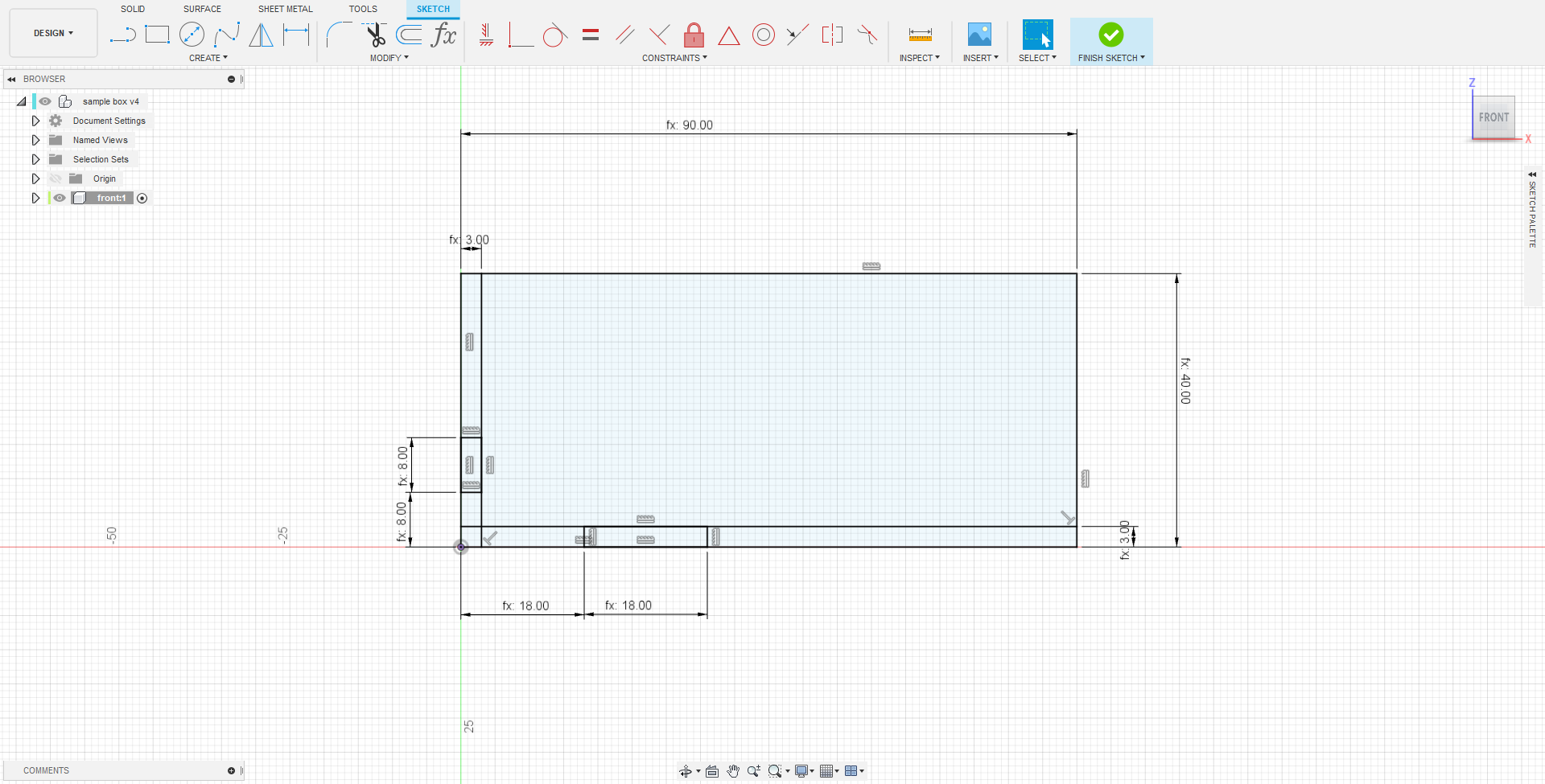
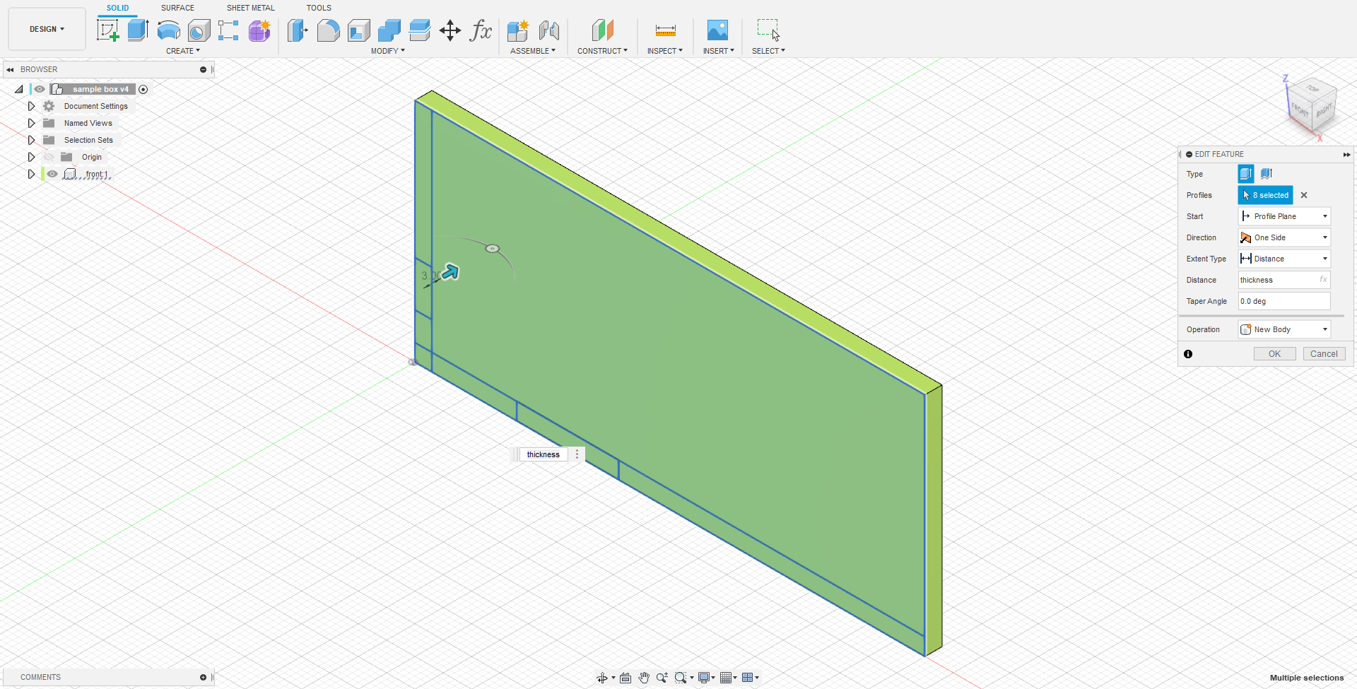
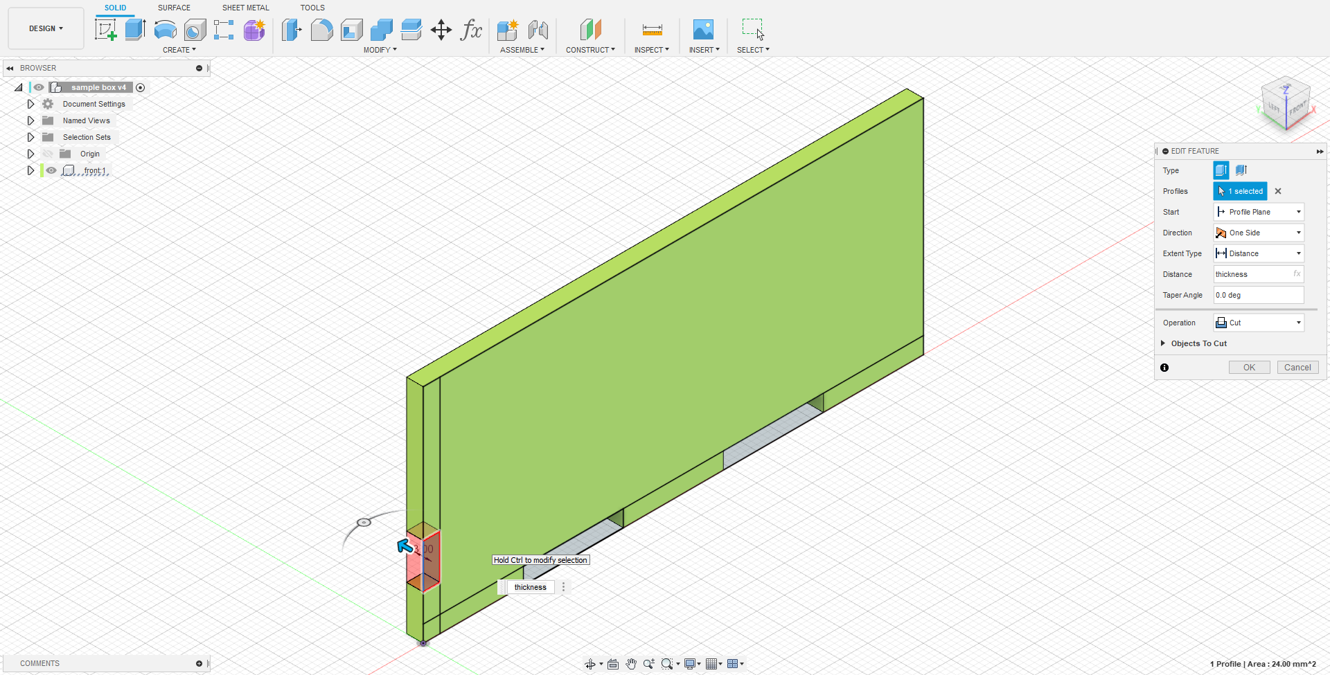
First a rectangle sketch was drawn and extruded for the front face. The sketch was dimensioned using the parameters length and height mentioned above. A tab and the tab spacing for the length and height is drawn as well, but for now the whole rectangle is extruded to the thickness set earlier.
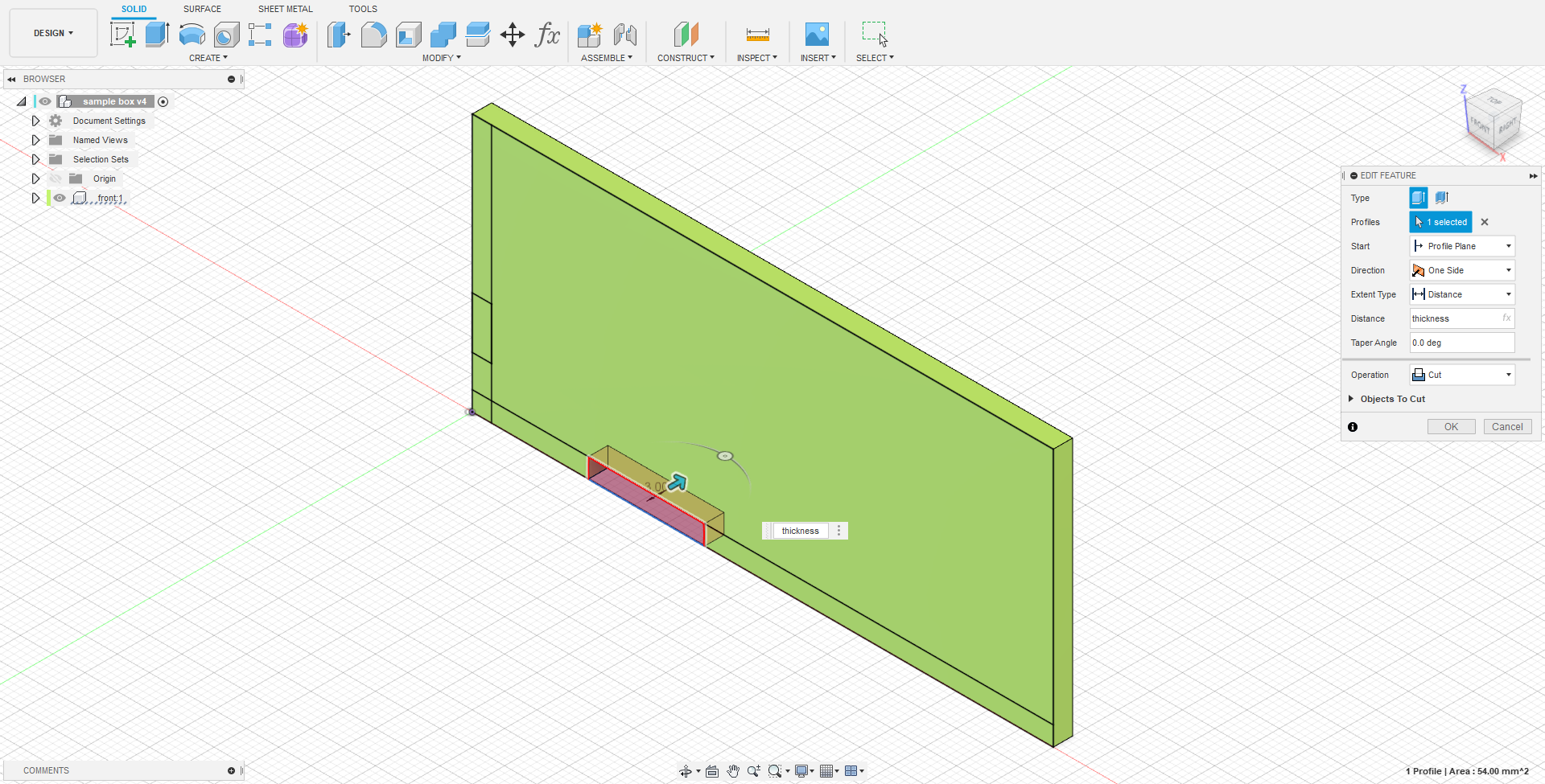
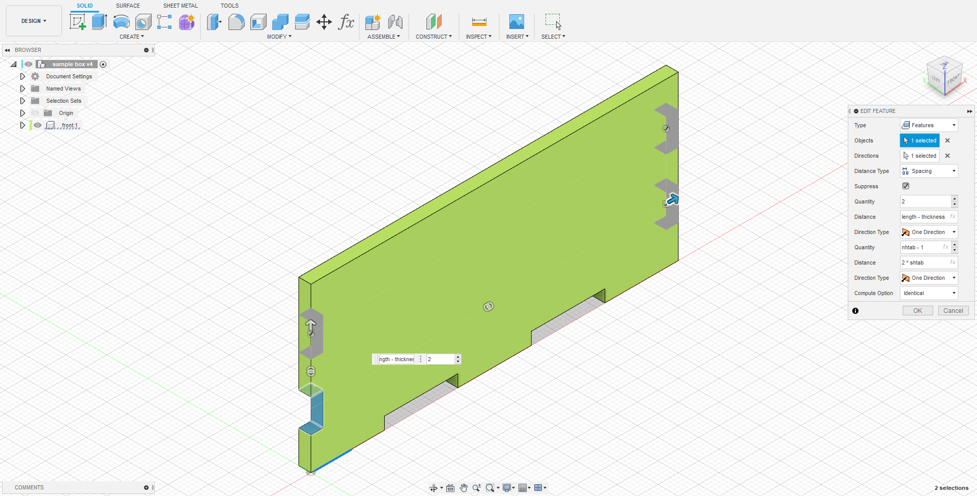
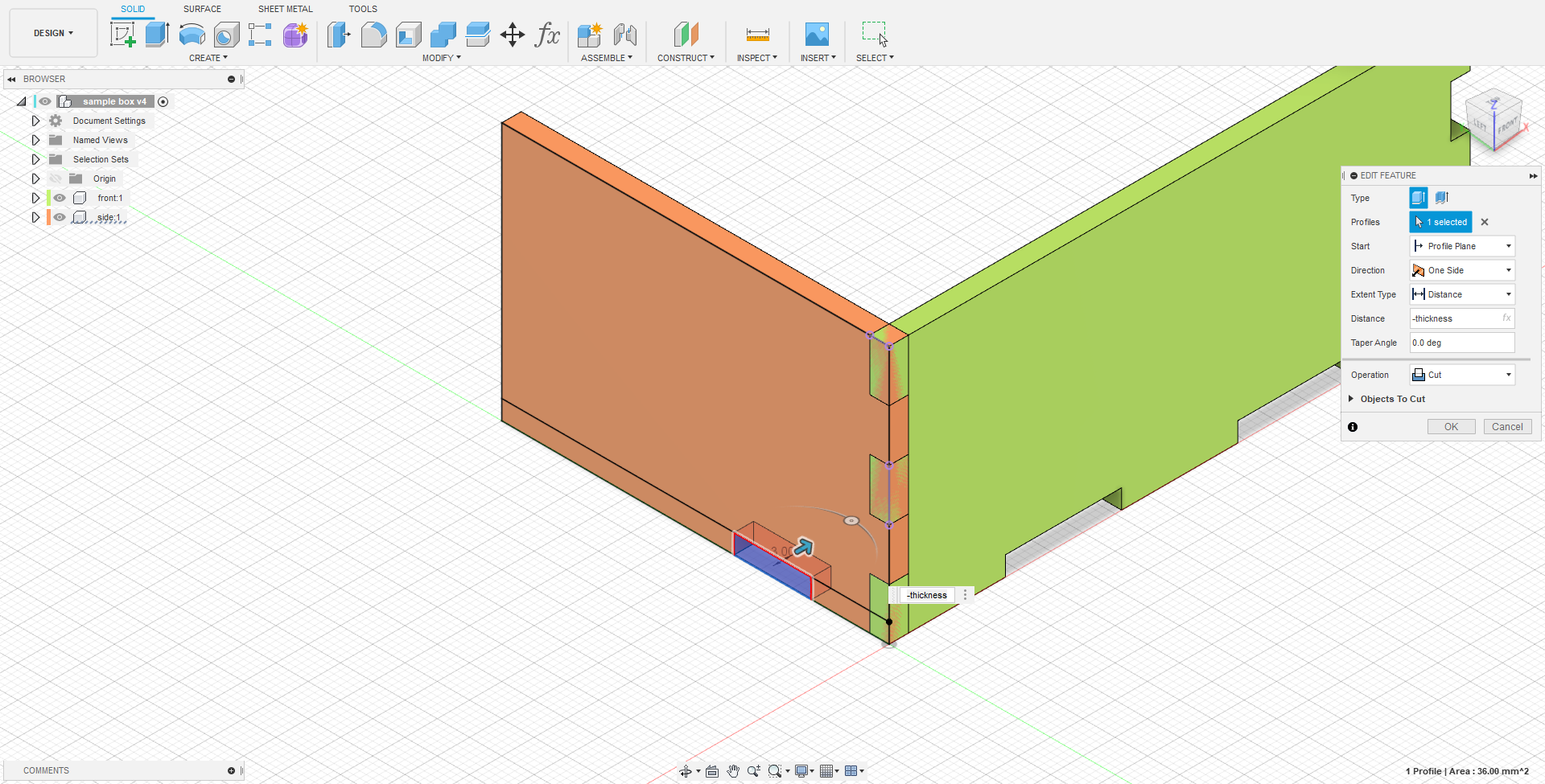
The tab spacing on the length was then cut. This allows the tab spacing to be a feature instead of being baked into the sketch, which will allow me to use rectangular pattern to pattern it along the length.
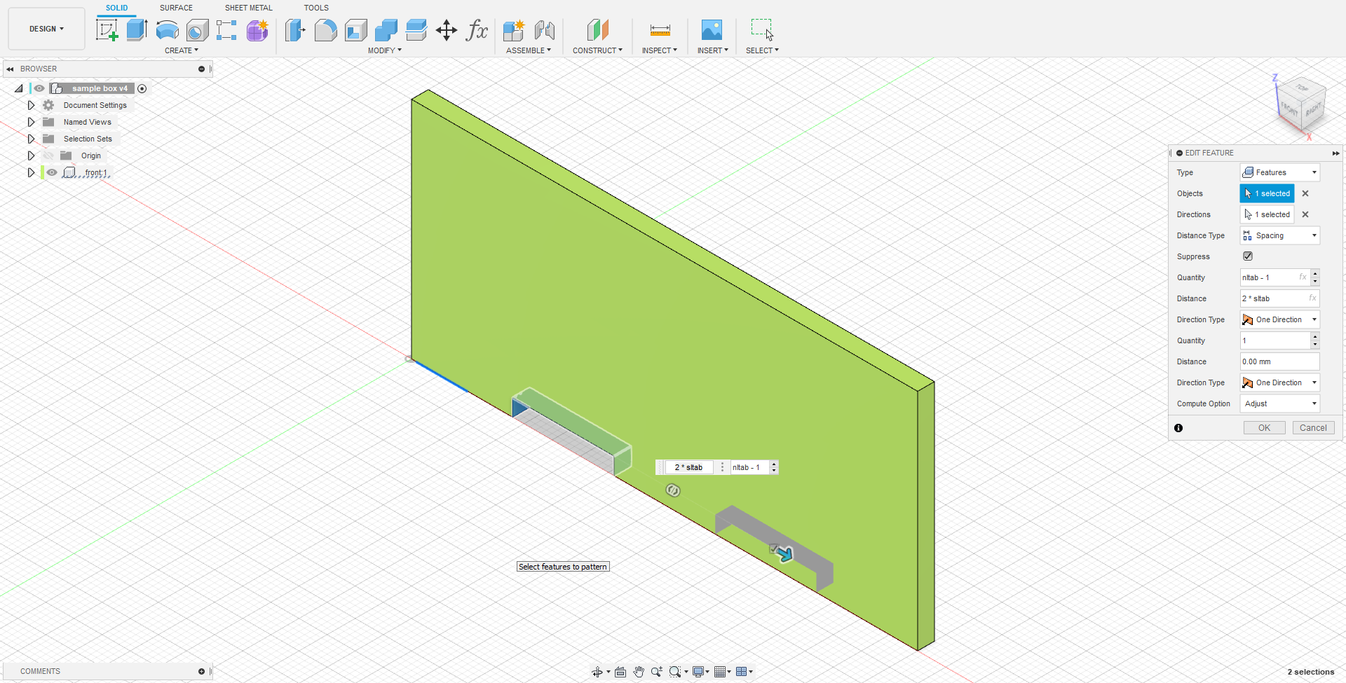
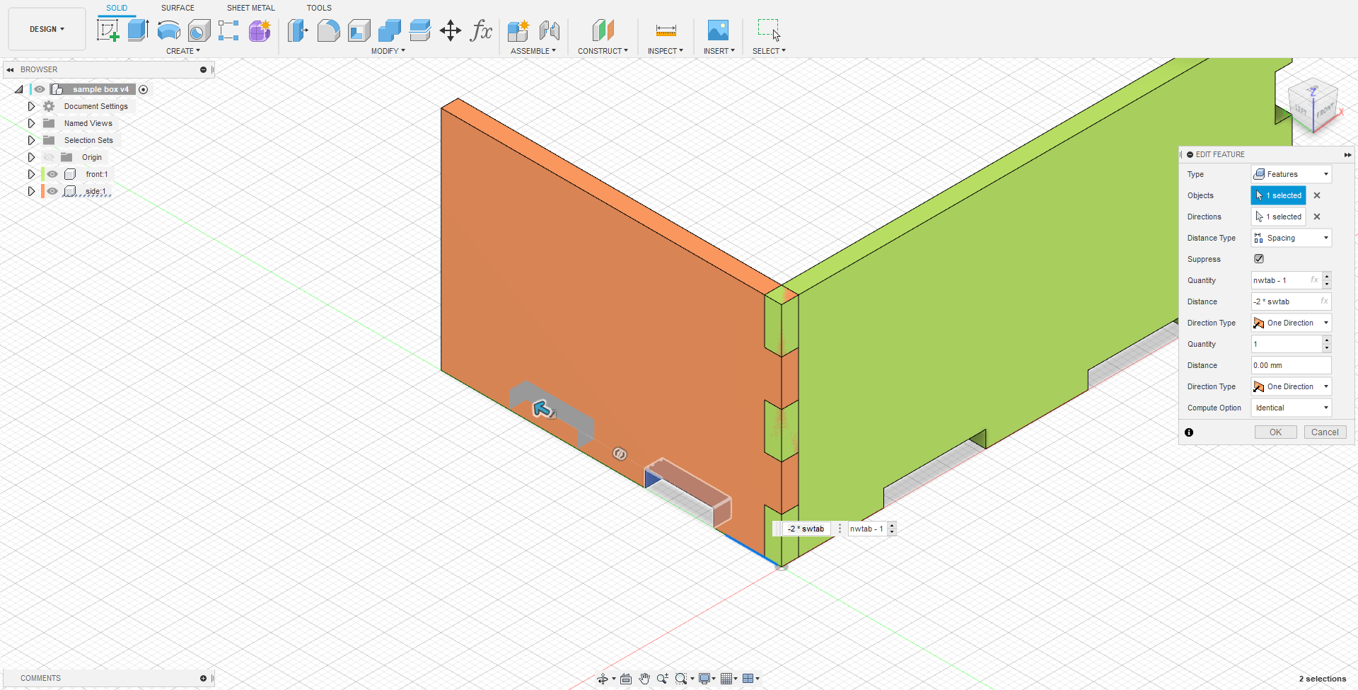
The same was done to the tab on the height, but the feature was patterned in 2 directions such that the opposite side of the front face also has tabs. And with that the front face is done for now.
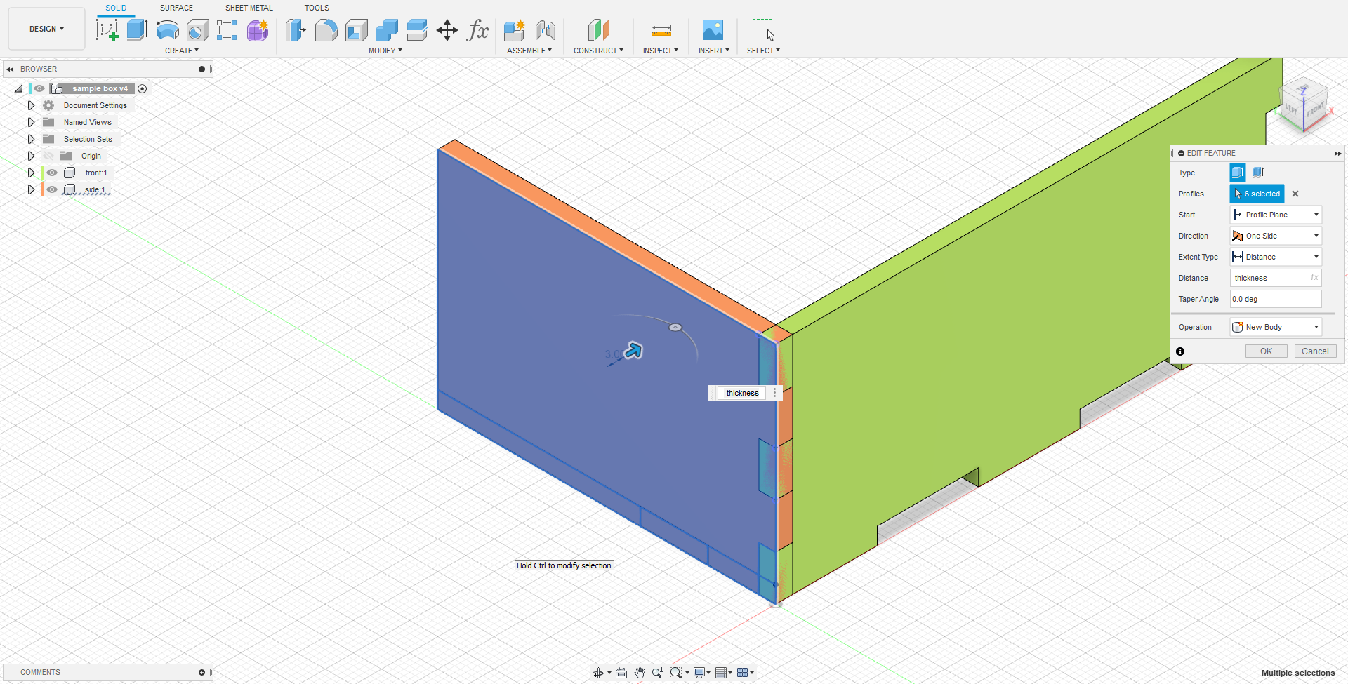
Moving onto the side, first a new component was made using the front face as a parent. The sketch was dimensioned using the parameters width and height mentioned above and is anchored to the edge face of the front tab. In this case, only a tab and the tab spacing for the width. Just like earlier, the whole rectangle is extruded to the thickness, intersecting the front face.
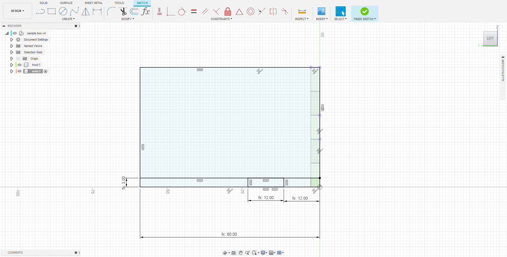
The tab spacing on the width was cut, then rectangularly patterned to get the tabs on the width of the box.
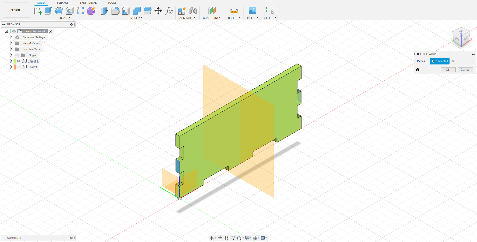
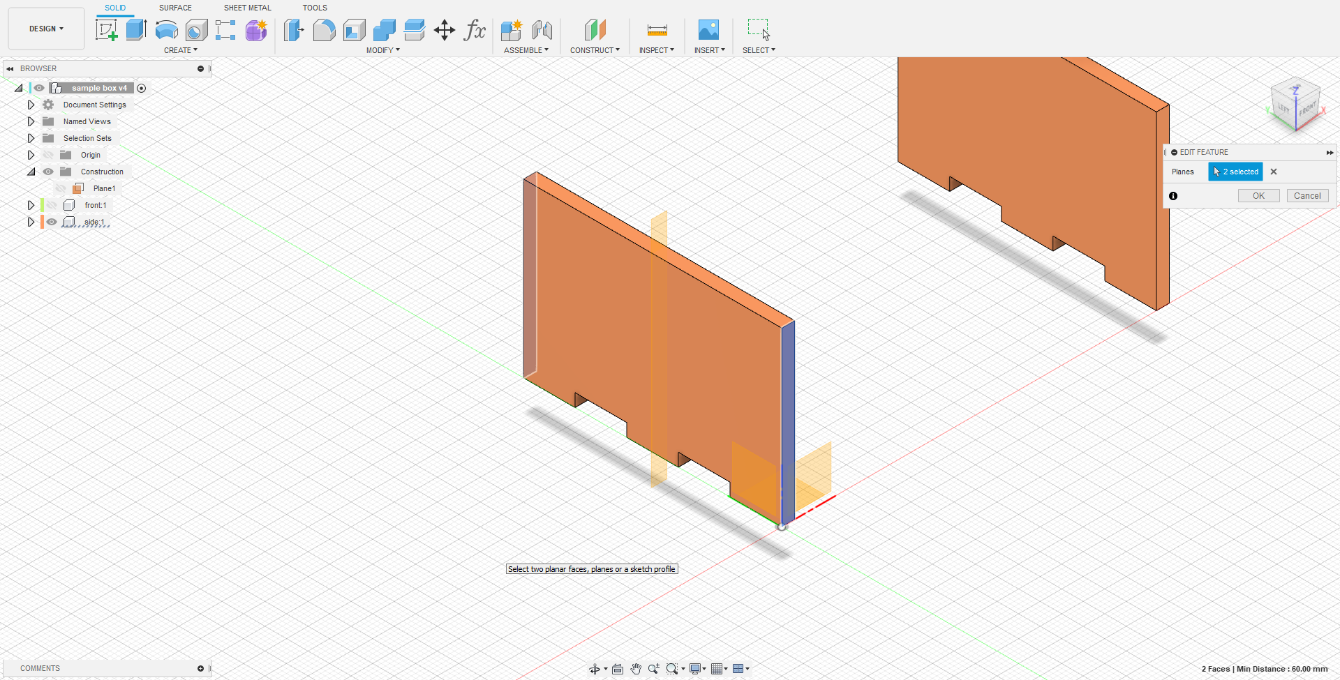
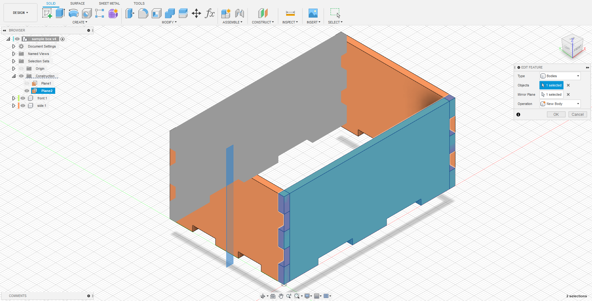
To mirror the side plate, a plane that bisects the front face was first constructed using midplane. The side plate was then mirrored to the other side.
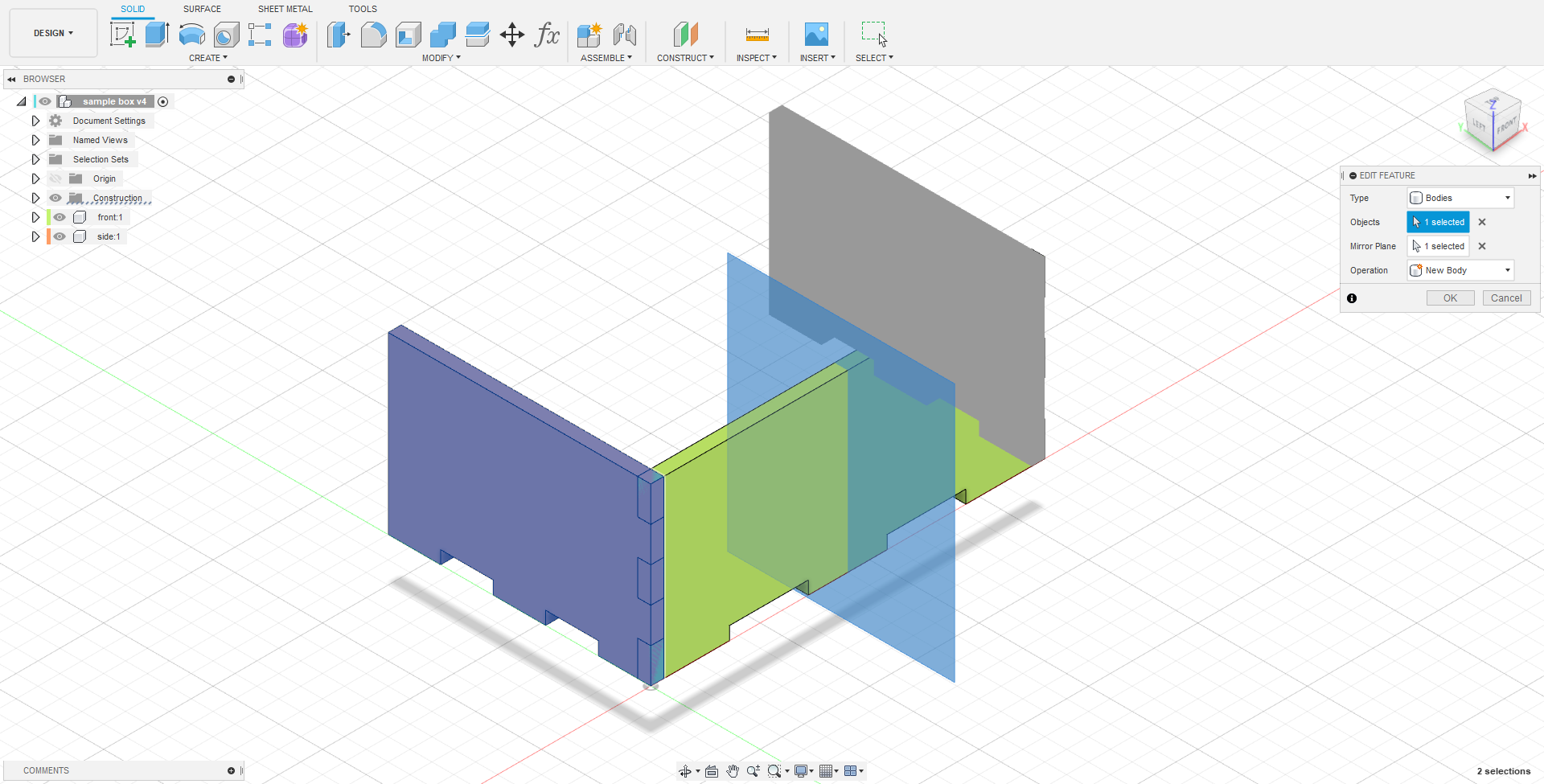
The same was then done to the front plate.
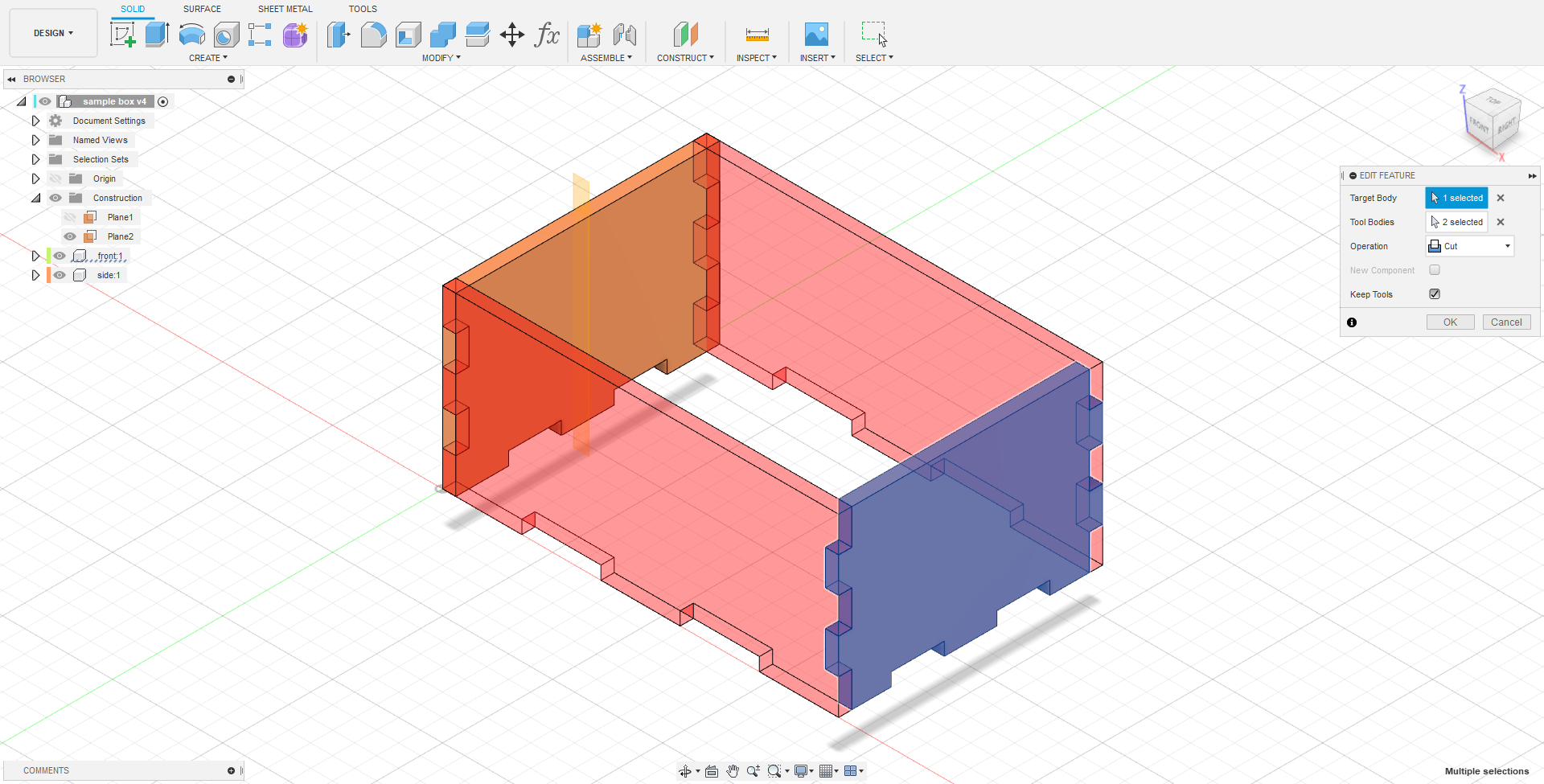
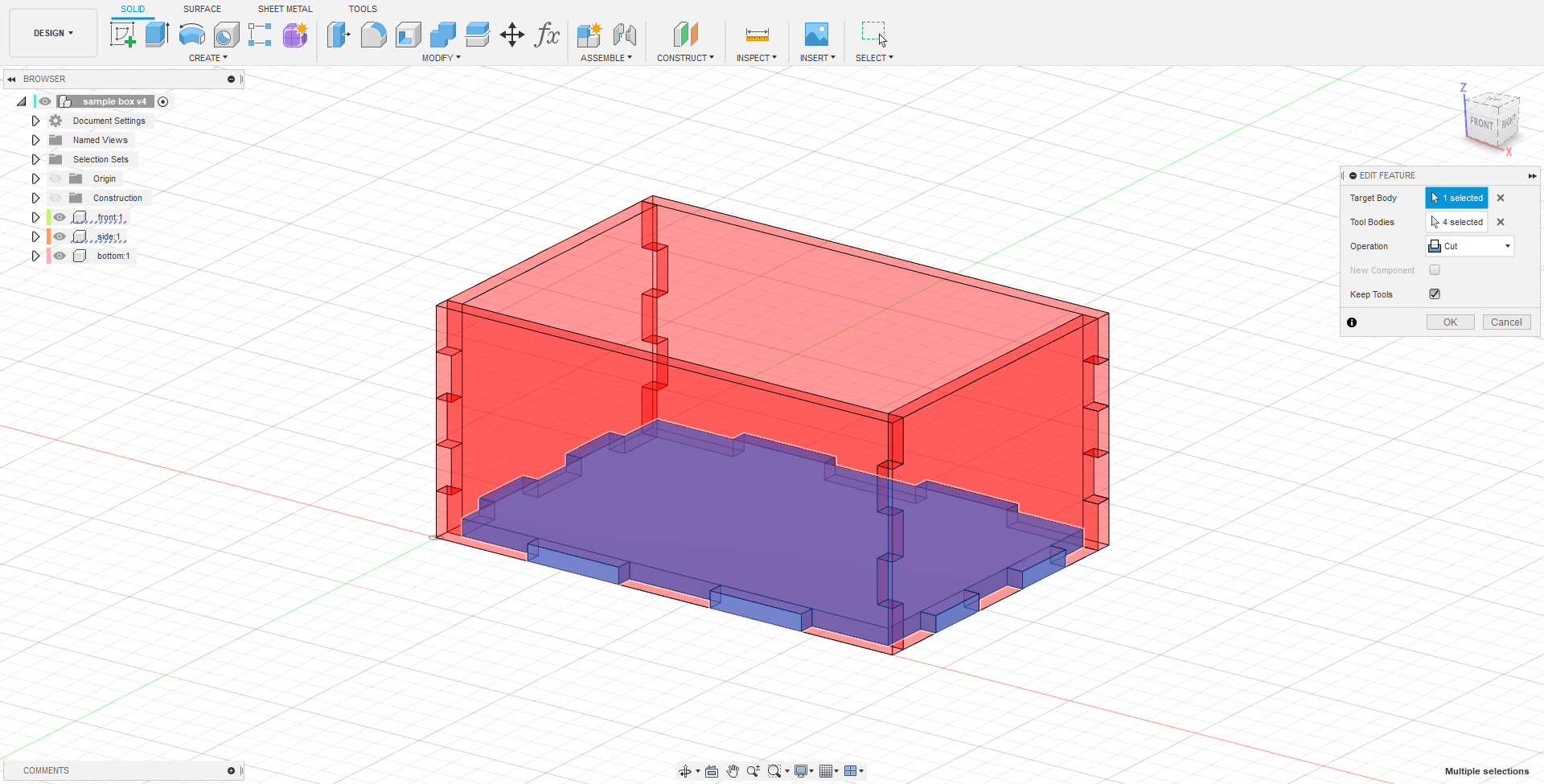
To get the remaining tabs on the sides, the combine tool was used. Using the front plate and its mirror as tool bodies and keeping tools, the tabs are cut out of the side plate.
The same was done on the other side.
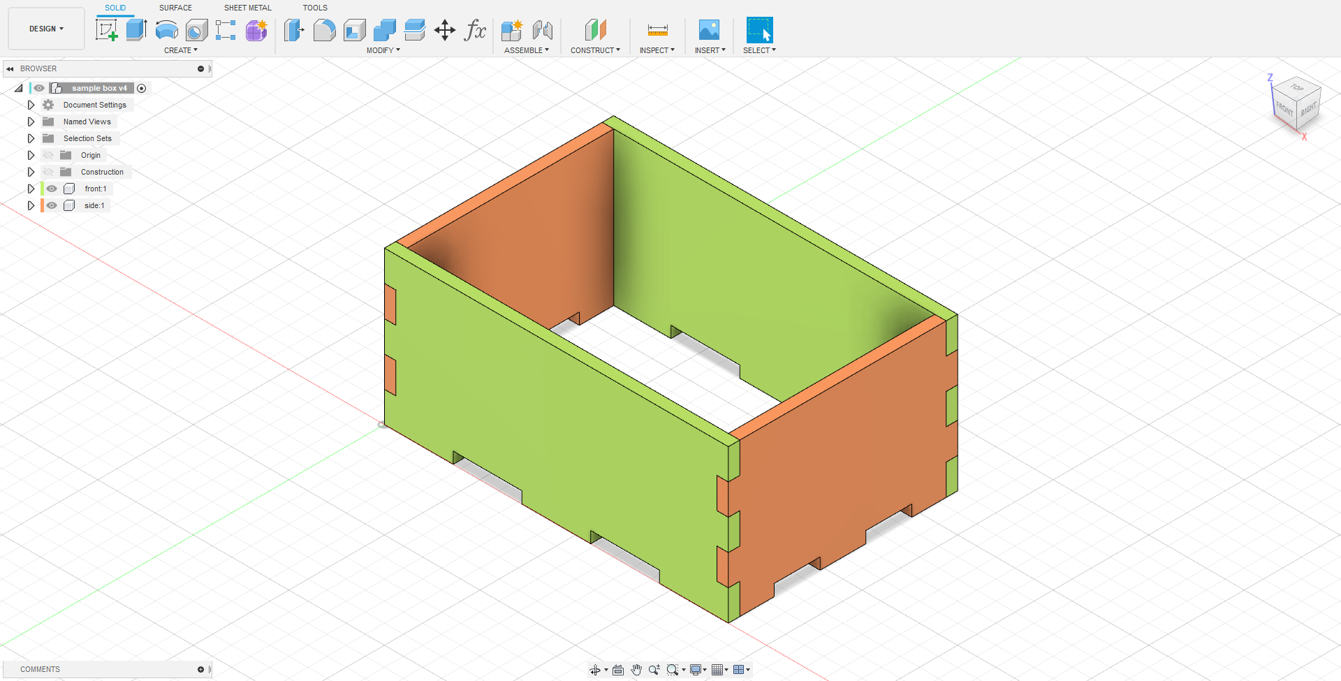
To make the bottom, a new component was made. A rectangle was sketched and constrained to the edges of the sides I already had. The rectangle was then extruded to the thickness, intersecting the existing sides.
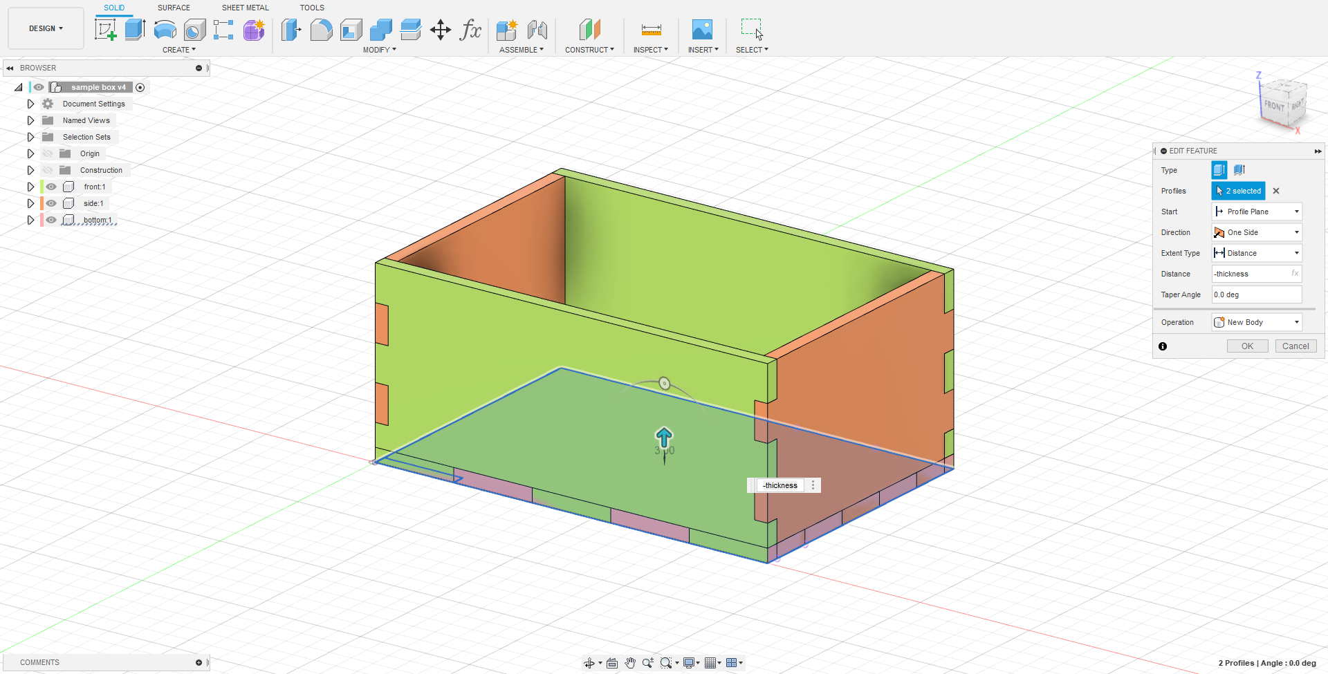
The tabs on the bottom were then cut using the combine tool. The existing sides were chosen as the tool bodies and the tools were kept after the cut. With that, the main box assembly was done.
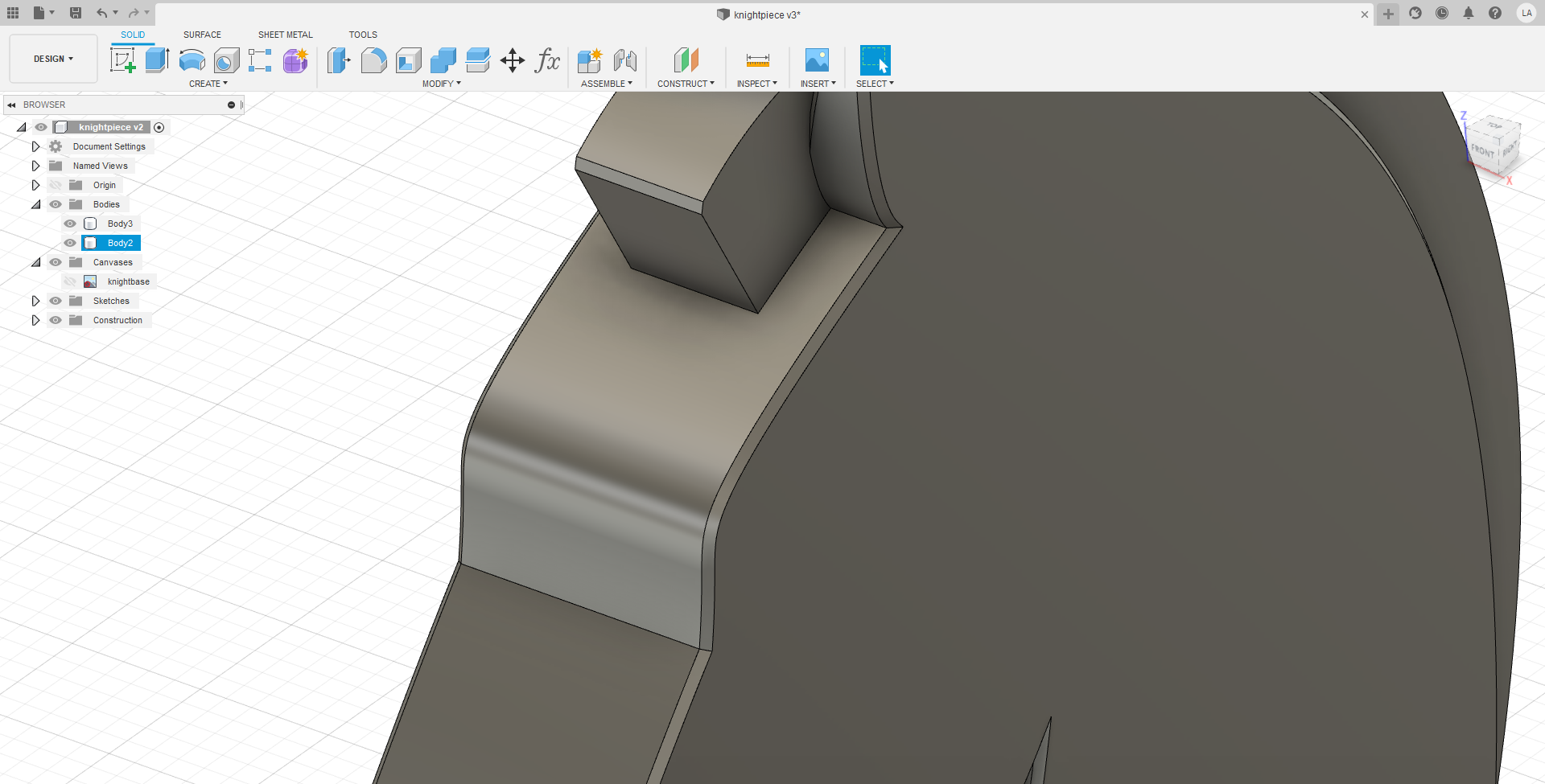
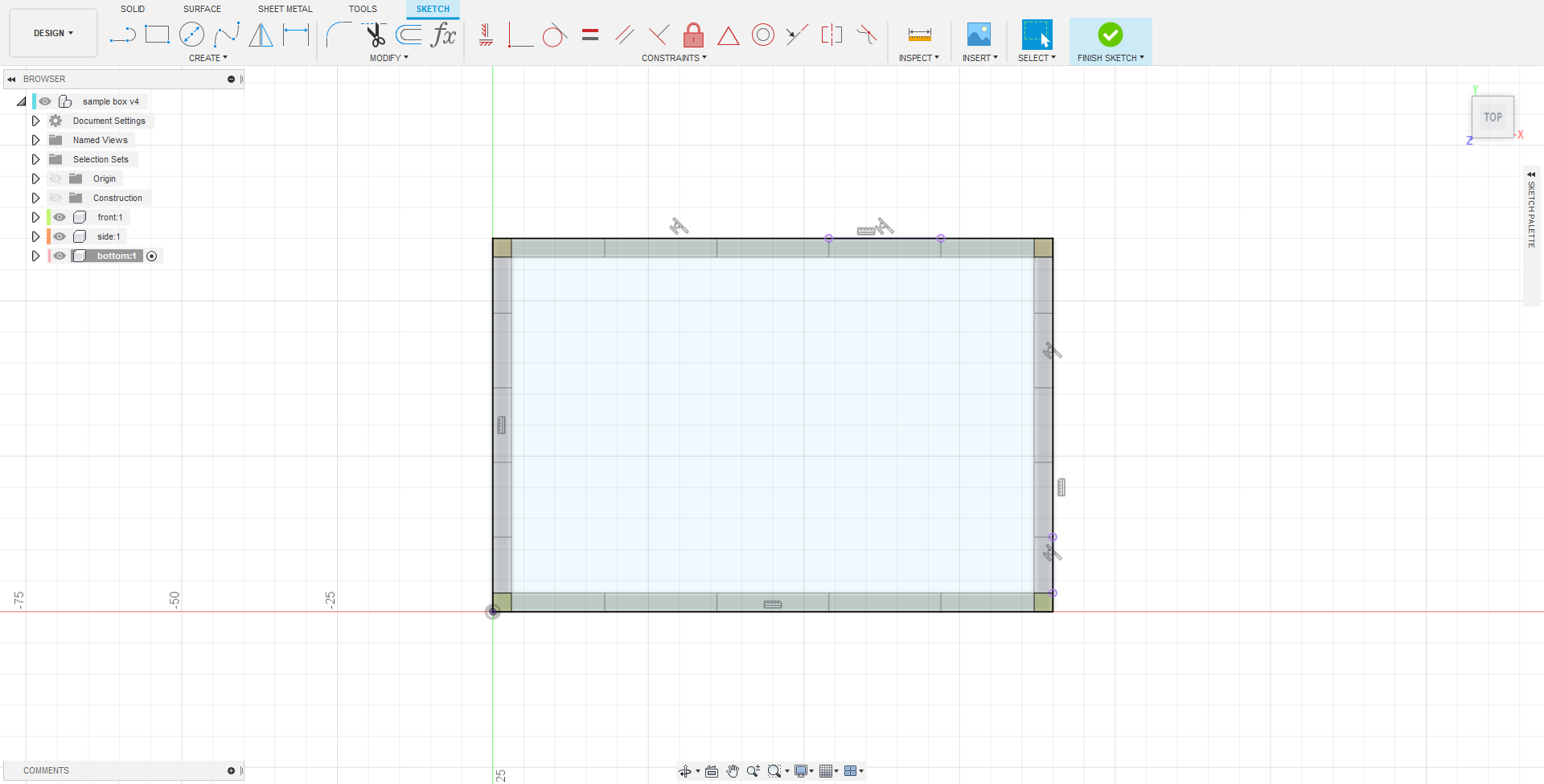
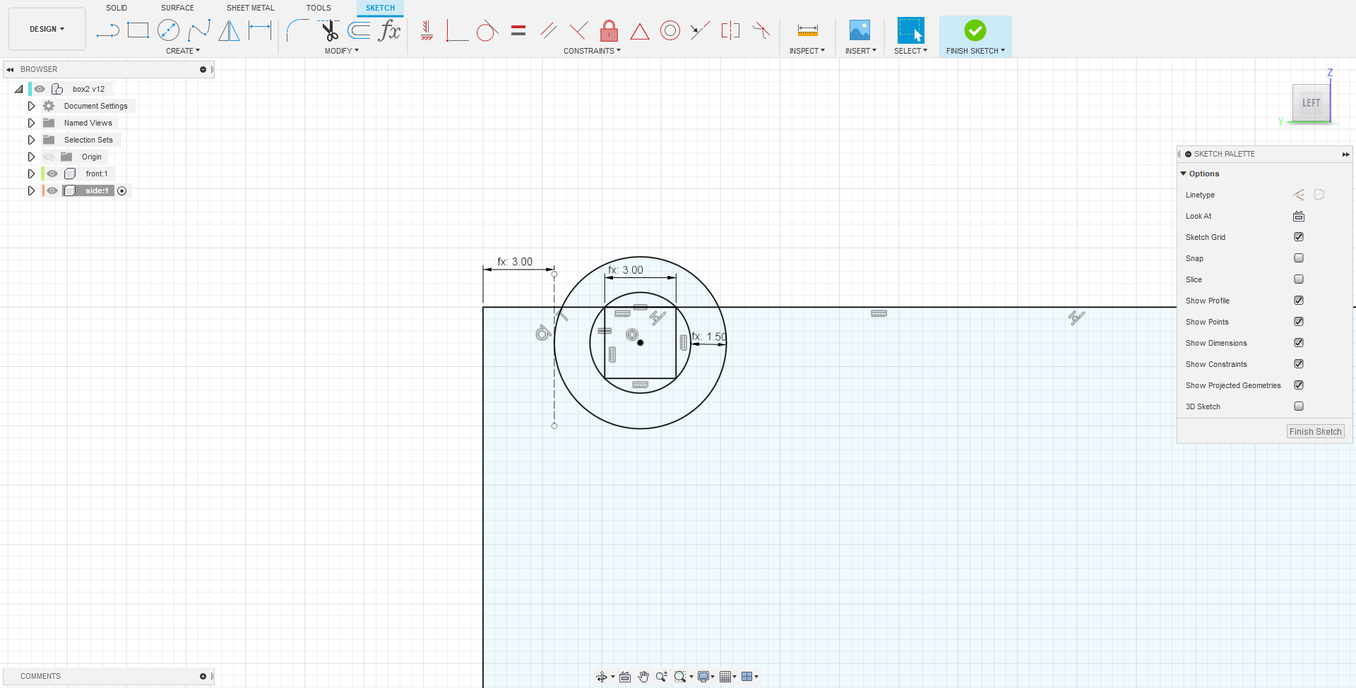
To make a movable lid on the box, I kept it simple and made a “Square peg in round hole” hinge. I went back to the original side sketch and added the hole for the hinge. The shape was constructed by first inscribing a construction square with a side length being the thickness in a circle which will become the hole. The construction square represents the “pin” of the lid. Another circle was then drawn concentric to the hole 50% of the thickness larger than the hole. The top of the square was then constrained collinearly to the top edge of the front and the edge of the larger circle is dimensioned thickness length away.
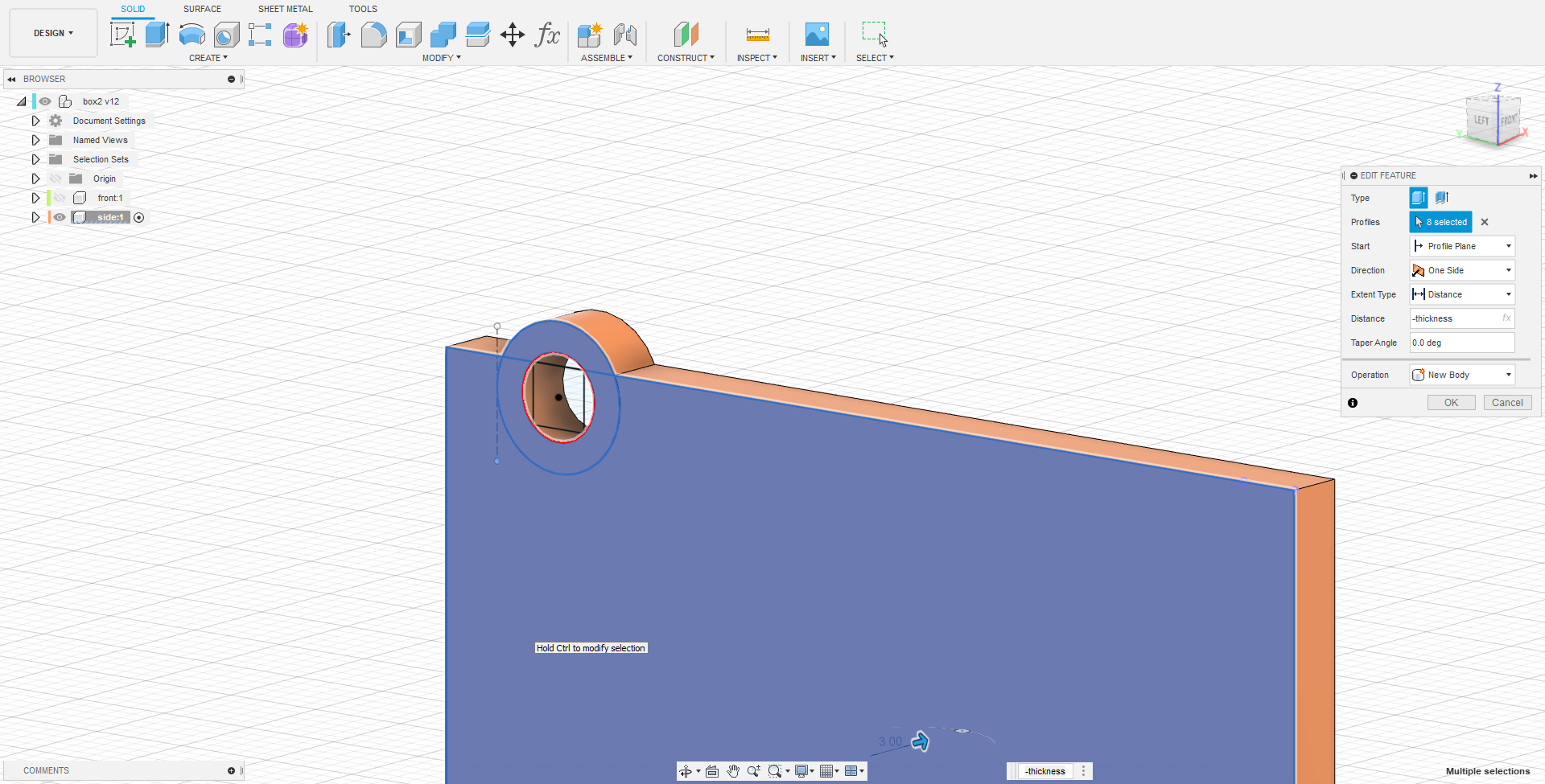
The front extrude was then updated with the new sketch and the rest of the model updated itself accordingly.
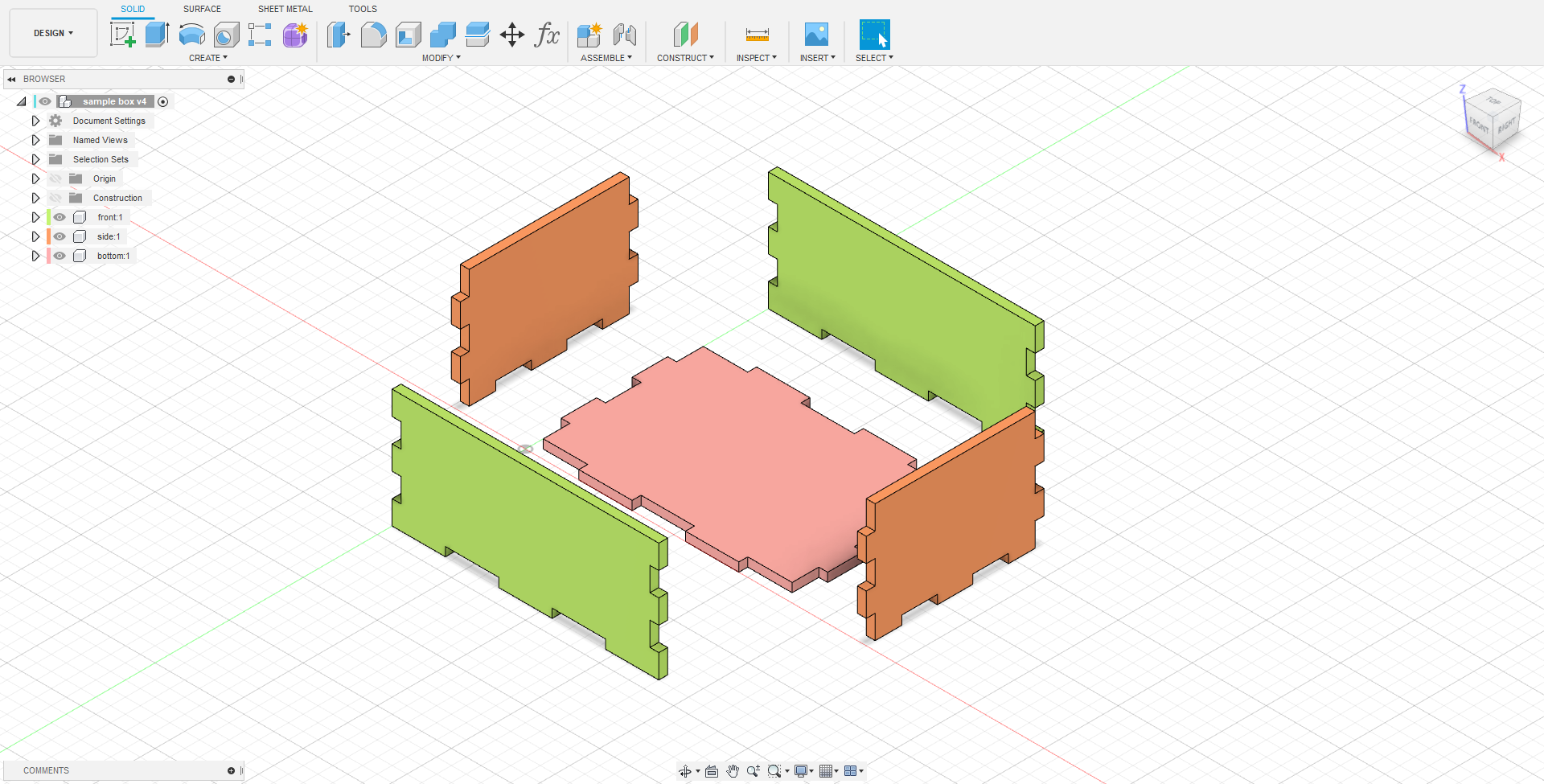
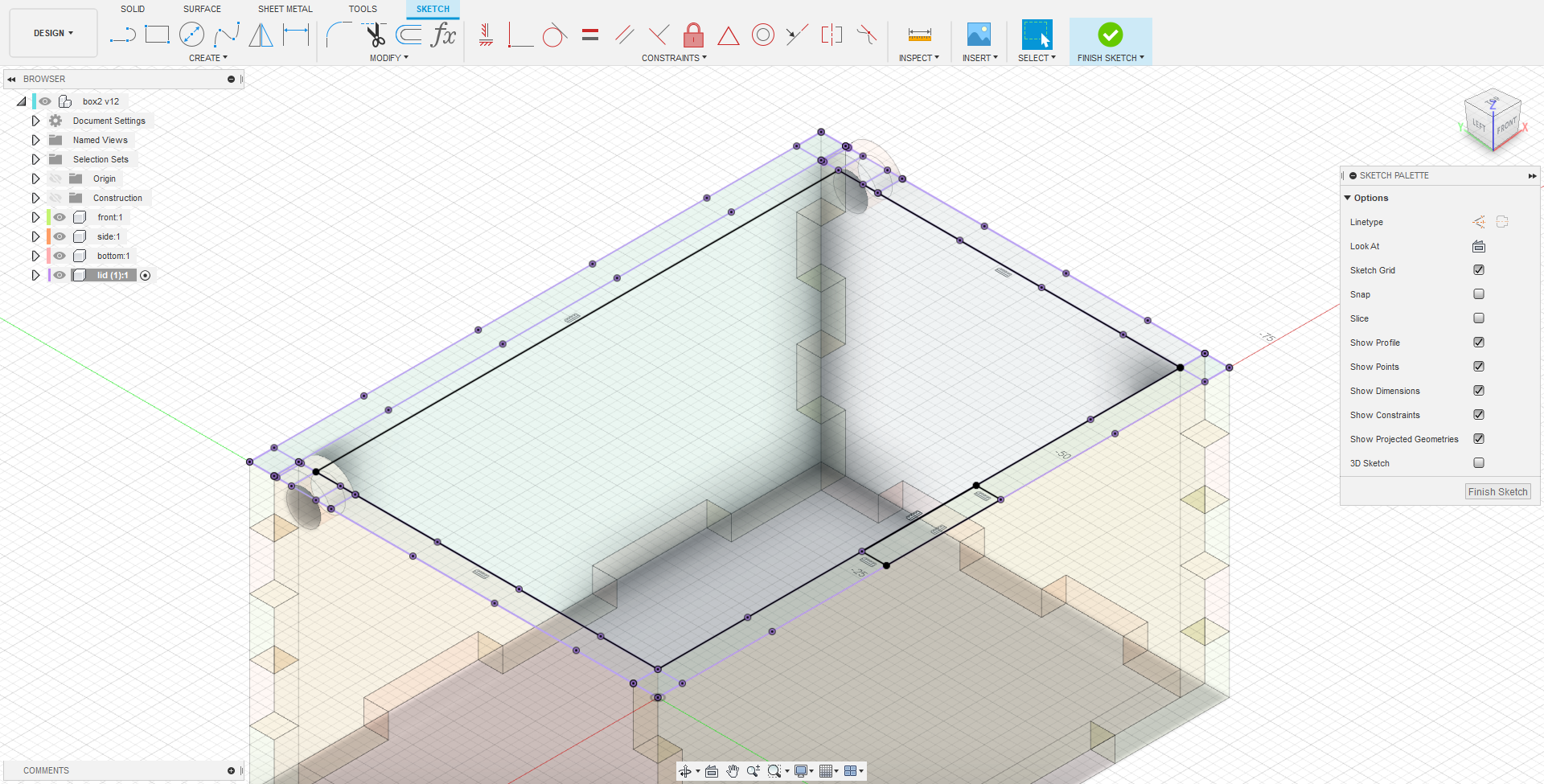
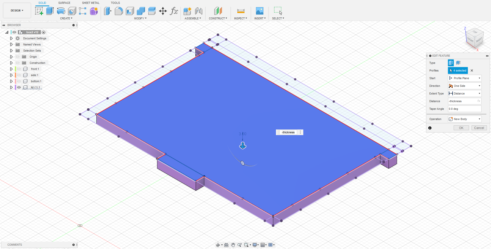
To make the lid, first a new component was made. The sketch was drawn on the top of the box. Cut edges were projected. A tab was constructed on the lid in order to make it easier to open.
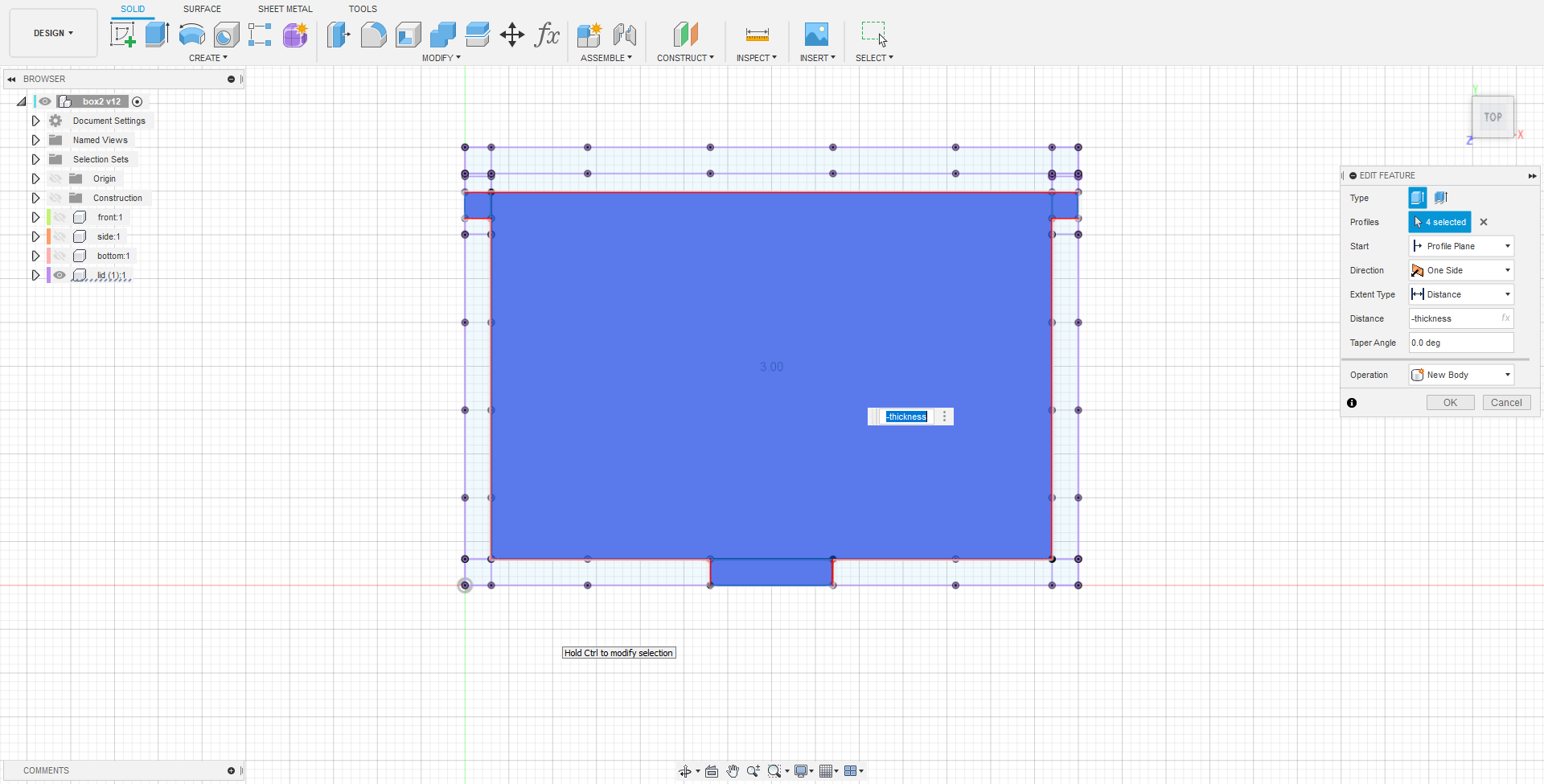
Finally, the sketch was extruded to the thickness, completing the lid. With the lid completed, the box is done for now, at least for the construction of it.
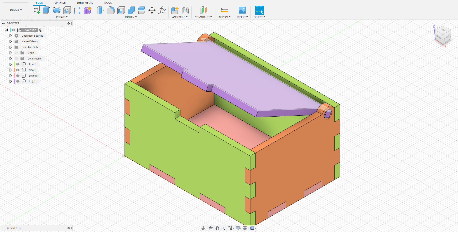
Embedded 3D model
Other 3D Models done
Nametag
Laptop Stand
Useless Mug