CAD System
Using Fusion 360
Fusion 360 is an integrated CAD, CAM and CAE software which allows us to perform many tasks that are useful in the module, such as making designs for both 3d printing and laser cutting. Being from an engineering course, I took a module in year one called Computer Aided Drafting, which introduced me to AutoCAD and Autodesk Inventor. As such, using Fusion360 felt familiar to me. Nevertheless, I still viewed some tutorials on using Fusion360 as a refresher, mainly videos by [Kevin Kennedy]. One of the things I relearnt while going through the tutorials was the importance of constraints and dimensioning.
Constraints and dimensioning are the bread and butter of CAD drawings. It allows us to anchor the drawing to real world values, eliminating uncertainty in our designs.
Drawing Exercises
Skip to:
[Exercise 1][Exercise 2]
Exercise 1
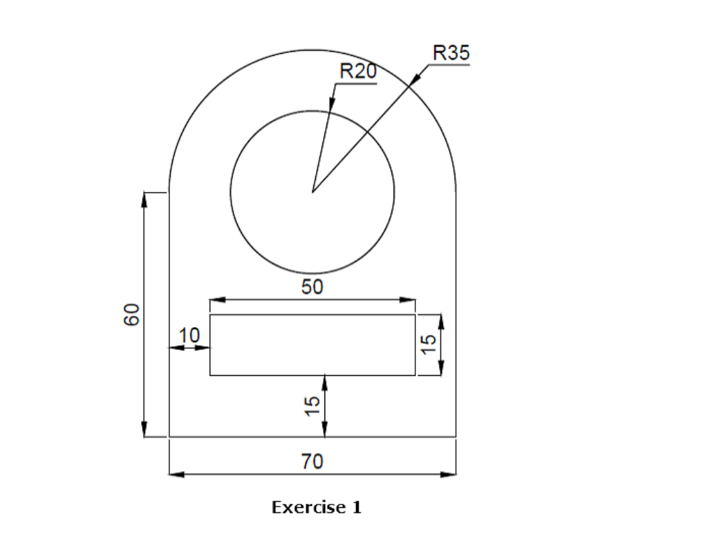
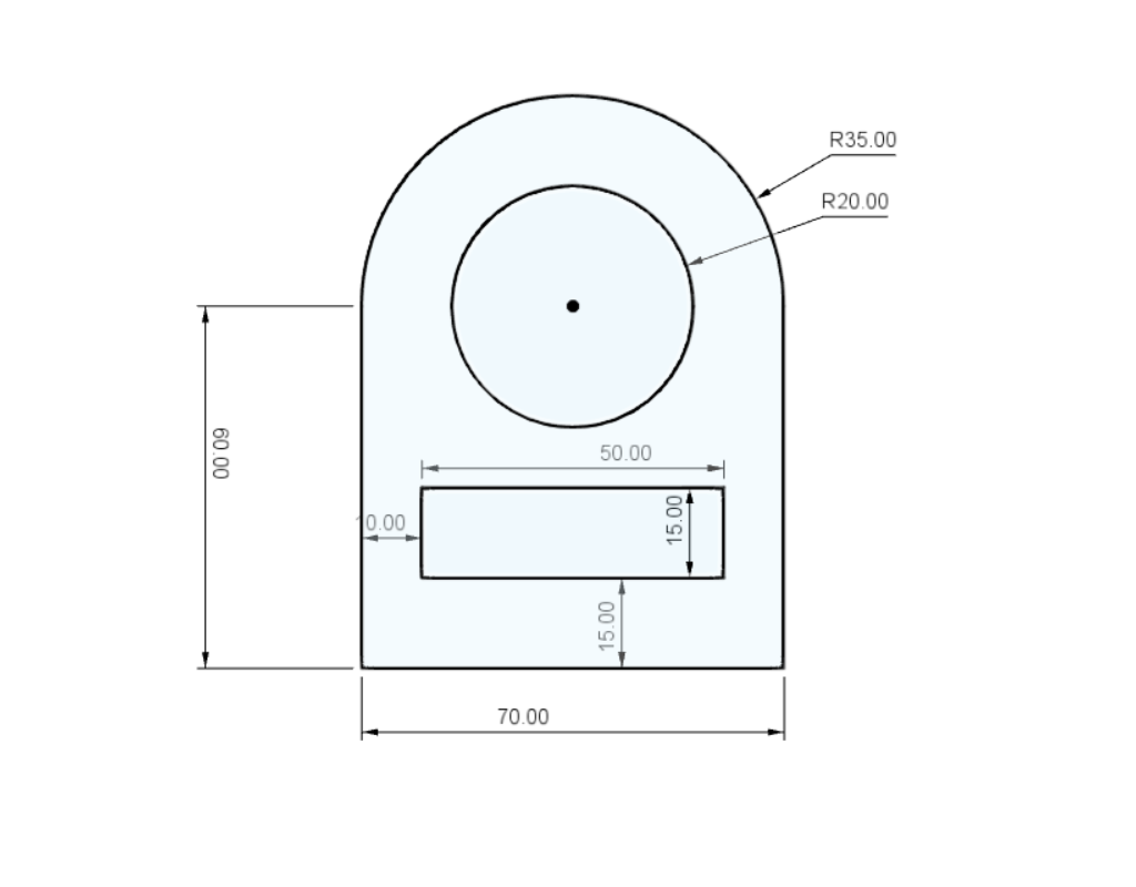
Exercise 1 served as a hands-on refresher on the tools used in Fusion 360. It was quite simple but fun to do. The drawing consists of just simple lines and a few circles constrained and dimensioned together.
Exercise 2
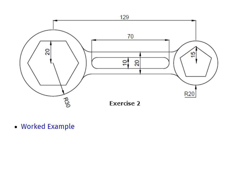
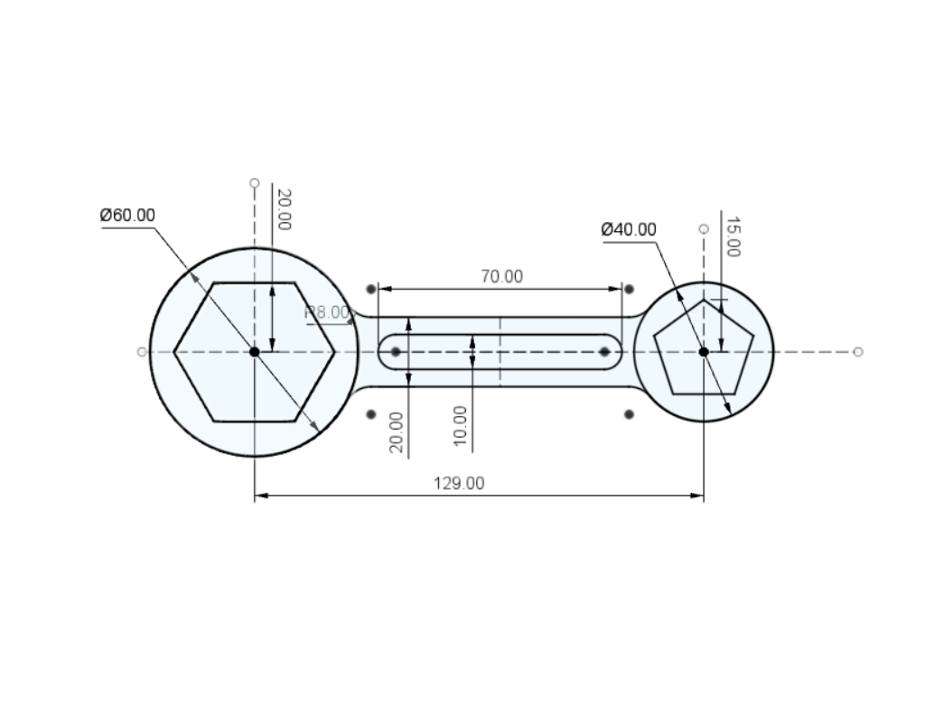
During exercise 2, I faced one problem with drawing, which was that once the polygons were placed and initially dimensioned, I was unable to change its dimensions and number of sides after that. That was when I learnt about parametric drawings, introduced to me by my lecturer.
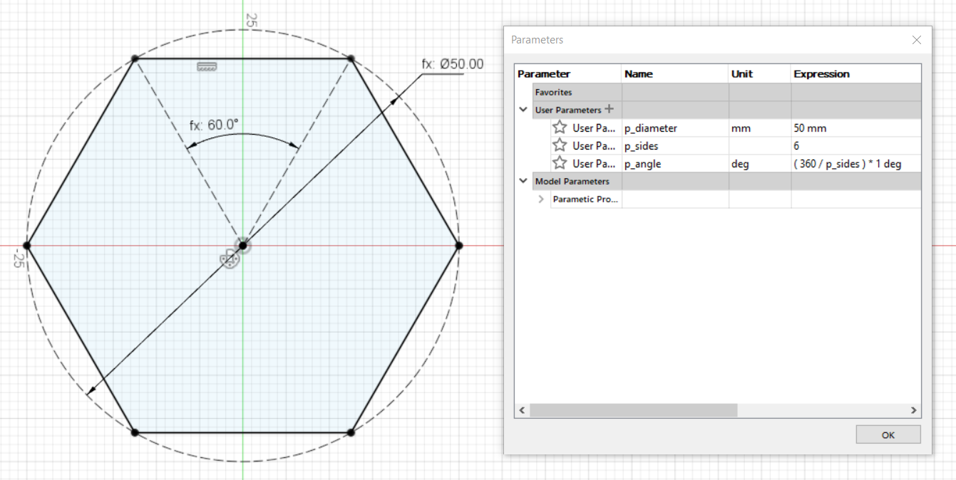
By drawing the hexagon in a different way instead of using Fusion360’s built in polygon drawing tool, I was able to change whatever parameter of the polygon whenever I want. This not only extends to making polygons, but also in changing the dimensions of multiple features in a design.
While it may not be that useful or downright a hassle in smaller projects, it will be very helpful in projects that require many copies of a certain feature that has to be consistent across the project. I will definitely be using more parametric drawings in the future