Arduino and Electronics
Skip to:
[555 Timer][Counting 7-Segment Display]
[One Switch Many States]
[Resources Used]
555 Timer
Task: Convert the schematic into a TinkerCAD circuit and simulate it.
Simulation:
The 555 timer is configured as an astable using R and C values. The result is an alternating ON/OFF signal which flashes the LED.
Although quite a simple project, it did help me familiarise myself with tinkerCAD and allowed me to learn how to connect components on a breadboard.
Counting 7-Segment Display
Task: Write a program that counts from 0 to 9 continuously.
Simulation:
Explanation:
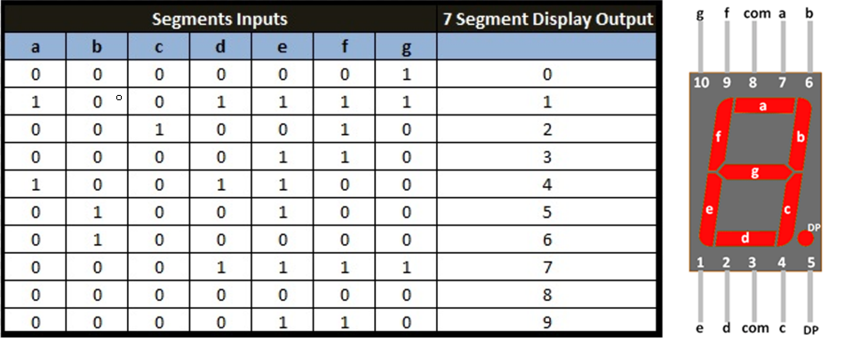
What we need to know before the code is the decoder truth table and the pin layout for the display itself. Each segment of the display is assigned to a letter, and by looking at the ‘1’s in the decoder truth table, we can see that each segment will only turn on for certain numbers.
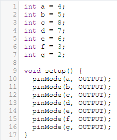
The code can be viewed in the simulation above. First, each segment is assigned to a pin on the arduino Uno. Then, the pins were setup to be output pins.
Next is the counting loop. For every value of 'i' below 10 starting at 0, the code first goes through with the displayDigit function, wait 1000 seconds, does the turnOff function then adds 1 to 'i'. Before 'i' reaches 10, the loop breaks and resets itself, starting back from 0.
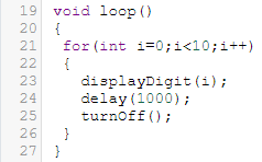
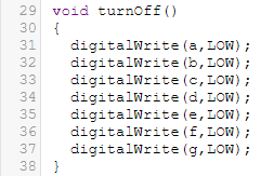
The turnOff function just tells the segments to turn off after each loop.
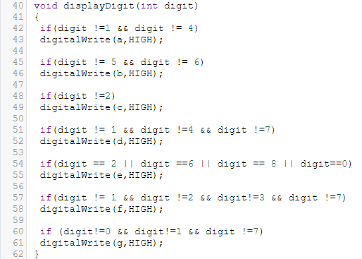
How the displayDigit function works is as explained earlier. Each segment will only need to turn on for certain numbers. For example, segment ‘a’ is turned for every number except 1 and 4. This means that when 'i' is either 1 or 4, the segment 'a' will be turned off, otherwise 'a' would be on. This is repeated for the other segments .
One Switch Many States
Task: Use a single push button to switch between 5 states for a group of 3 LEDs. The LEDs are to flash and after pressing the switch for 3 seconds, the system switches off all LEDs and returns to initial state.
Simulation:
Issues faced:
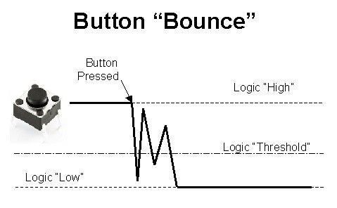
One of the issues faced was the bouncing of the switch that might cause incorrect states to be read. Without proper debouncing, multiple inputs may be read in quick succession when only 1 input is intended, which will cause issues in the code.
Another issue I faced was using delay for the flashing of the LEDs. However, I was not able to find the cause of this. Nevertheless, using millis() I was able to circumvent this issue.
Explanation:
Before explaning the code, it is important to understand millis(). millis() returns the number of milliseconds passed since the board began running the program. It acts as an internal clock and will be used multiple times during the assignment.
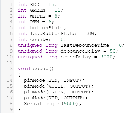
Just like assignment 1, each LED and button was assigned to a pin and variables were declared. lastDebounceTime, debounceDelay and pressDelay are unsigned long as the variables might need extra bits.
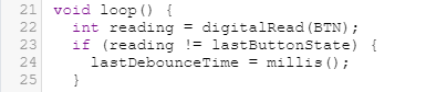
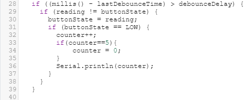
Next is the debouncing loop. First, the button reading is constantly taken. Once the button is pressed and the reading changes, the time millis() is taken and stored as the lastDebounceTime. Due to the bouncing of the switch, multiple readings will be taken and stored in quick succession.
At the same time, the difference between the current time and the stored lastDebounceTime is constantly being calculated. Once the difference exceeds the value set (in this case a delay of 50ms), it means that the switch has not "bounced" for 50ms and the input has settled. The next part of the code will be executed.
If the reading of the button is LOW (button pressed down), it will add 1 to the counter, which is initially 0. The number refers to the cases of the switch state, from 0 (inclusive) to 4. Once it goes beyond 4, the counter will reset to 0.
The different states are:
- 0 - All OFF
- 1 - RED ON
- 2 - GREEN ON
- 3 - WHITE ON
- 4 - All ON
In this case, ON/OFF refers to wether the LEDs are flashing or not.
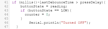
To turn off all the LEDs after pressing down the button for 3s, another 'if' statement is used in the loop. It works in the same way as the debounce delay, where it compares the lastDebounceTime and the current time and finds it difference. Once the difference exceeds the pressDelay (3000ms in this case), and the button is still pressed down, the counter is reset to 0, returning the LEDs to their initial states.
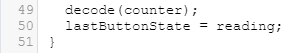
During all this, the function 'decode' has been continously run and change in counter will cause a switch in state. The lastButtonState is also being continously updated.
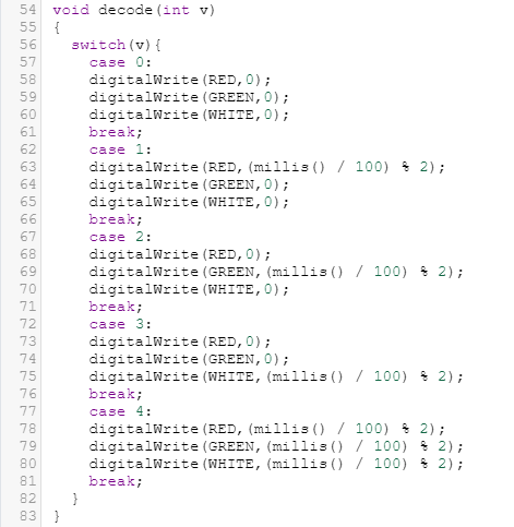
The function decode contains the switch states of the LEDs.
To make it flash, instead of delay, millis() was used. Adding delay caused problems with the input but I could not figure out why as of the writing of this documentation.
The basic principle is that it takes the millis() reading at a certain point in time and finds the remainder when divided by 2, which results in either a '0'(OFF) or '1'(ON). However, just using millis() will cause the LED to blink every millisecond, which would be too fast. As such, the reading is first divided by 100, which will cause it to blink every 100ms instead as it it will round the value to the nearest 100ms. The timing can be changed by changing this number.
Resources used
[Debouncing in Arduino][millis() in Arduino]
[Decoder Truth Table]
[7-Segment Pinout Diagram]
[Button "Bounce" Diagram]