Final Project
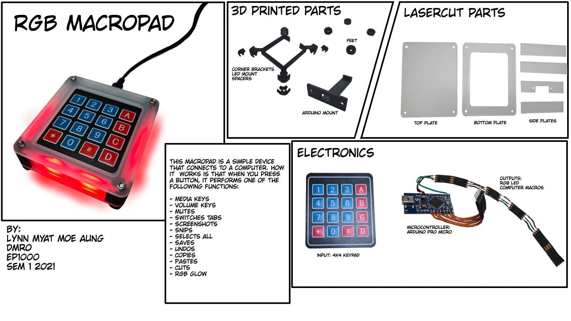
Here is where I will be documenting the process of making my final project. As this is my first full integration project, I wanted to make something simple. What I decided to make was an RGB Macropad, a convenient place with all the keybinds and media keys I need. I will be incorporating laser cutting, 3D printing and microcontrollers into a fully integrated project. The raw files can be aquired below and the rest of this page is my week to week documentation of the process.
Table of contents
List of Materials
Raw Files
Week 1
Week 2
Week 3
Resources Used
List of Materials
| Parts to purchase | Quantity |
|---|---|
| Arduino Pro Micro | 1 |
| 4x4 Membrane Keypad | 1 |
| WS2812 Neopixel | 6 |
| Frosted Acrylic Sheet | 1 |
| Parts to 3D print | Quantity |
| Center | 1 |
| Mount | 1 |
| Corner Spacer | 4 |
| Feet | 4 |
| Parts to laser cut | Quantity |
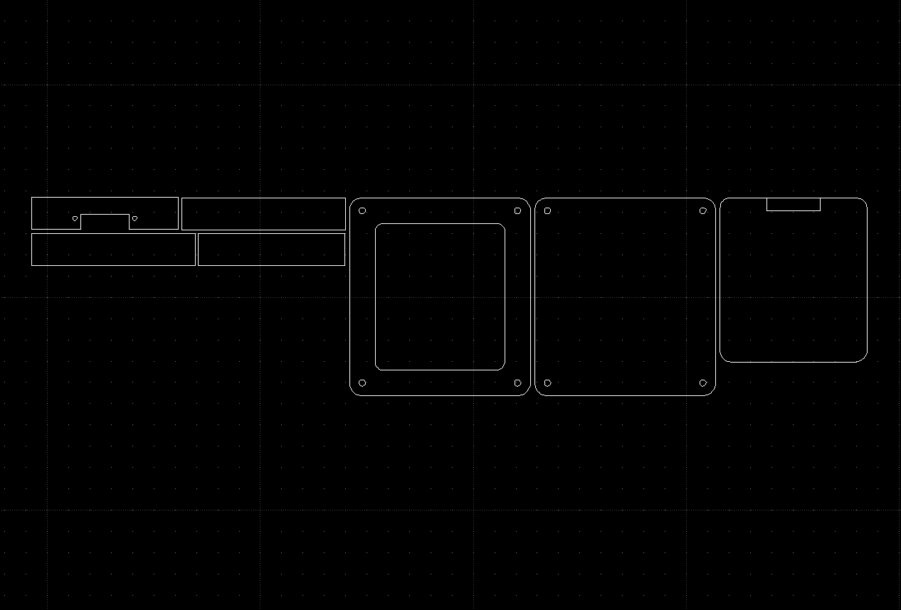
| Top Plate | 1 |
| Keypad Support | 1 |
| Front Plate | 1 |
| Back Plate | 1 |
| Bottom Plate | 1 |
| Side Plate | 2 |
Raw Files
[Google Drive folder with the raw files.]Week 1
Ideation
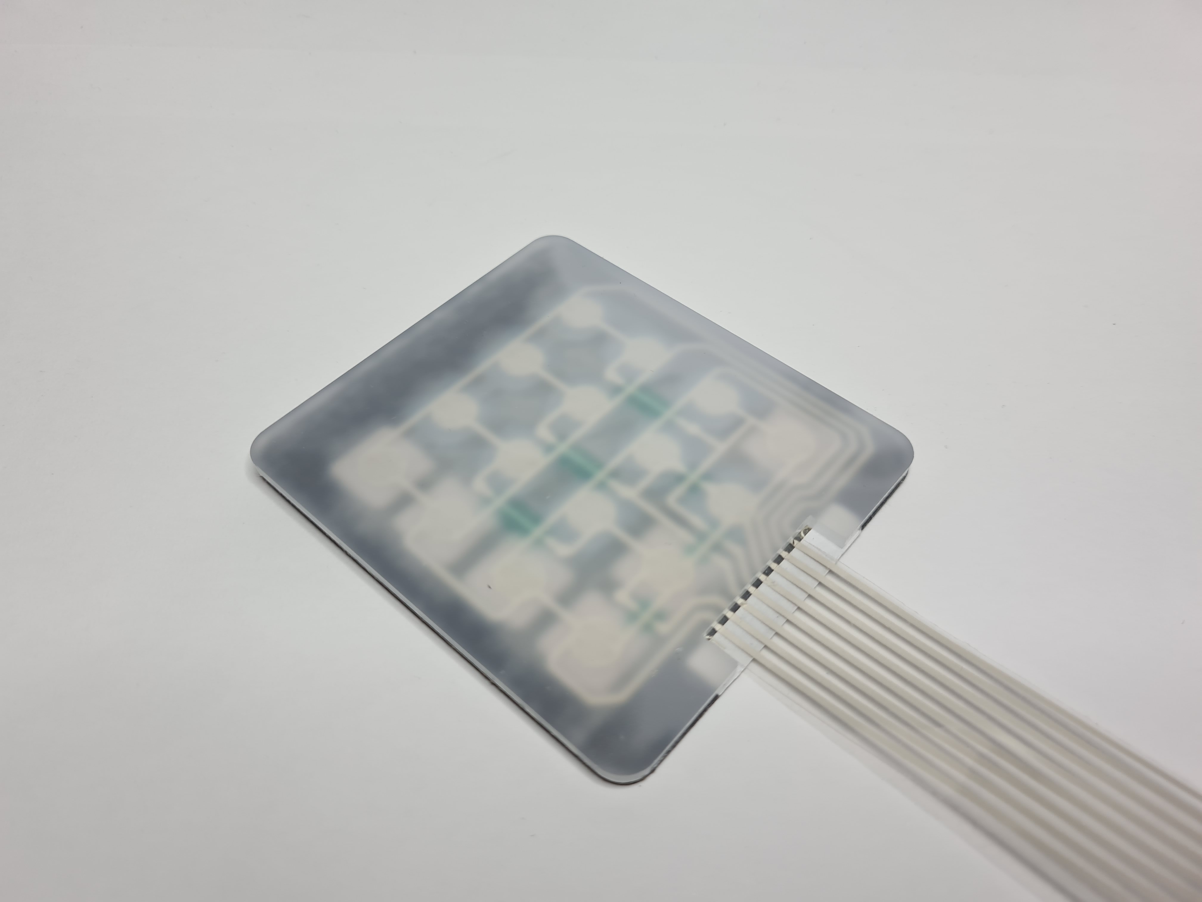
Originally, I wanted to make a mechanical tenkey pad for macros and shortcuts from scratch, soldering my own mechanical switches together in a switch matrix. However, because of the lack of time, I decided to use a 4x4 Matrix Membrane Keypad, which achieves the same purpose. With the main component decided, I went ahead and sketched out a basic case design. I took reference from https://create.arduino.cc/projecthub/brian-lough/the-simplest-diy-macro-keypad-d2e428 in order to learn more about the 4x4 matrix keypad.
Sketch
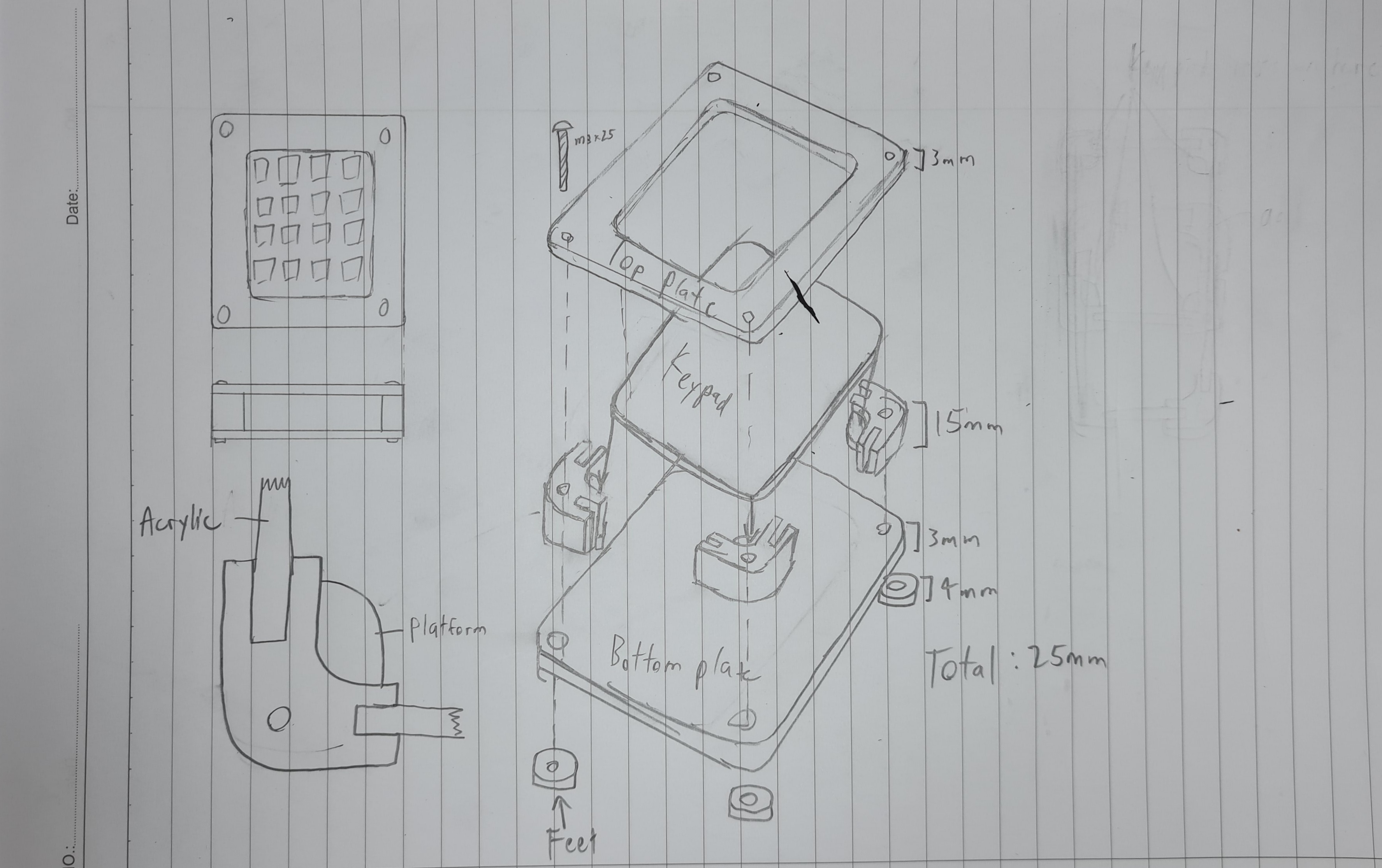
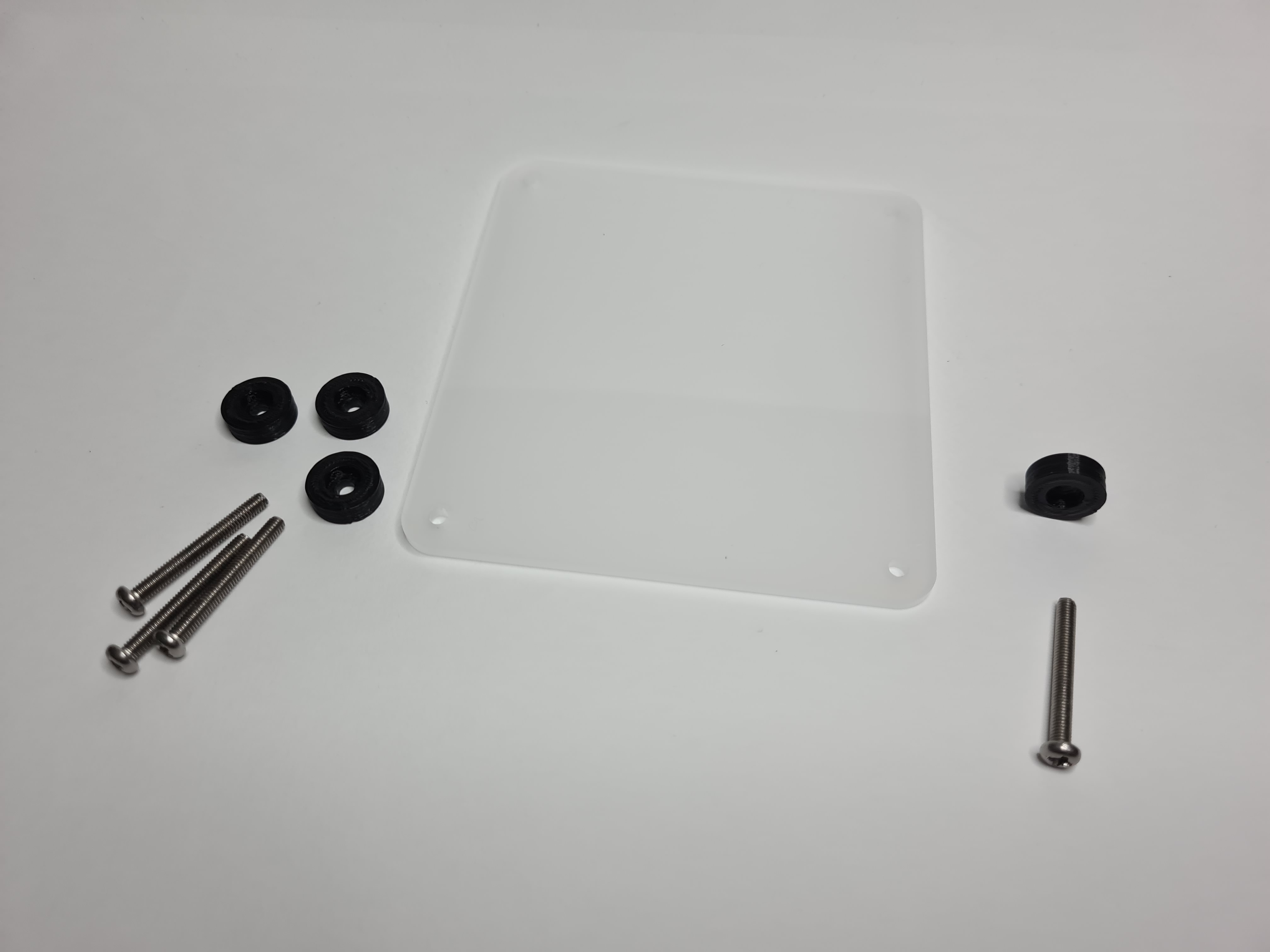
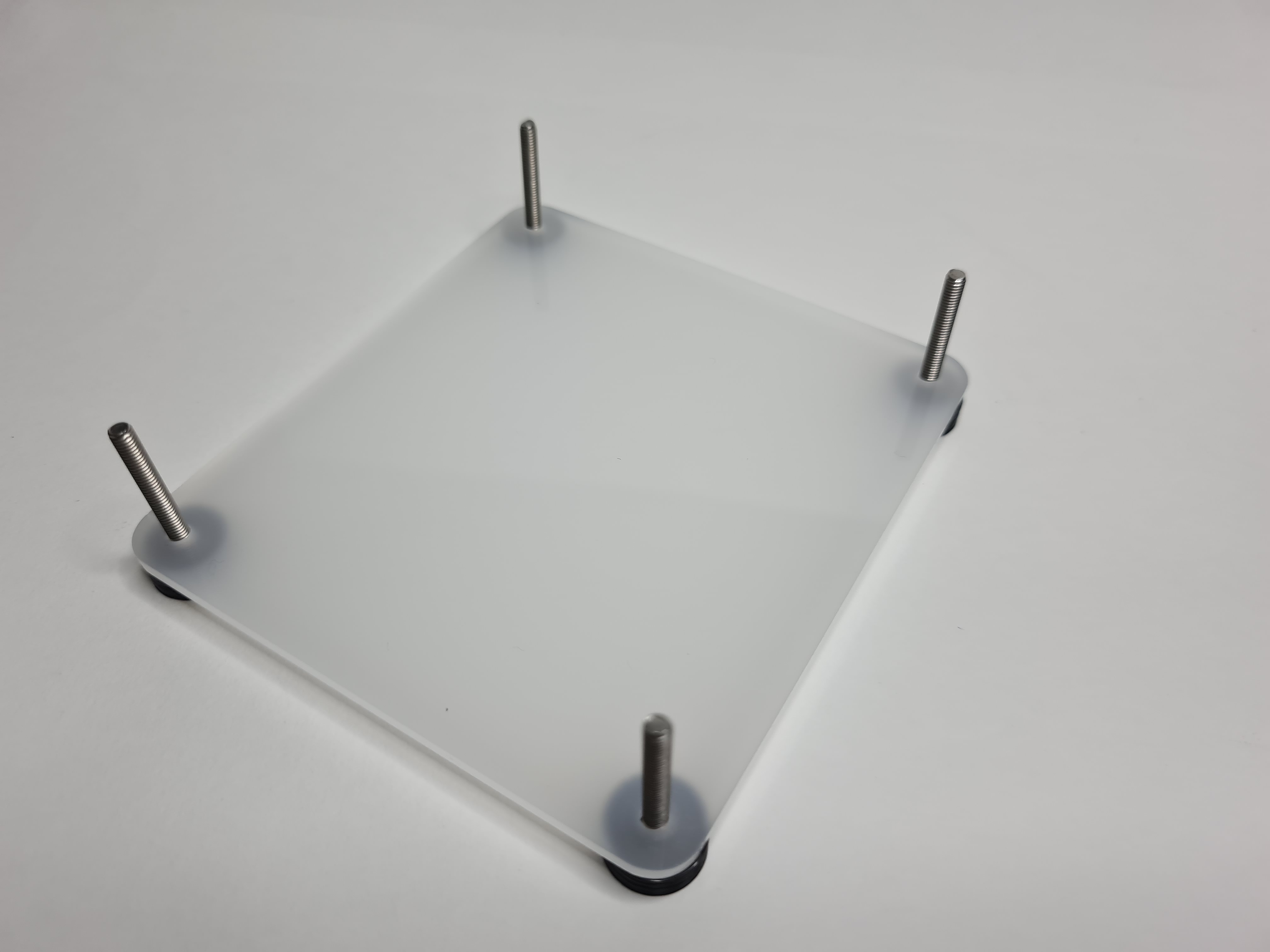
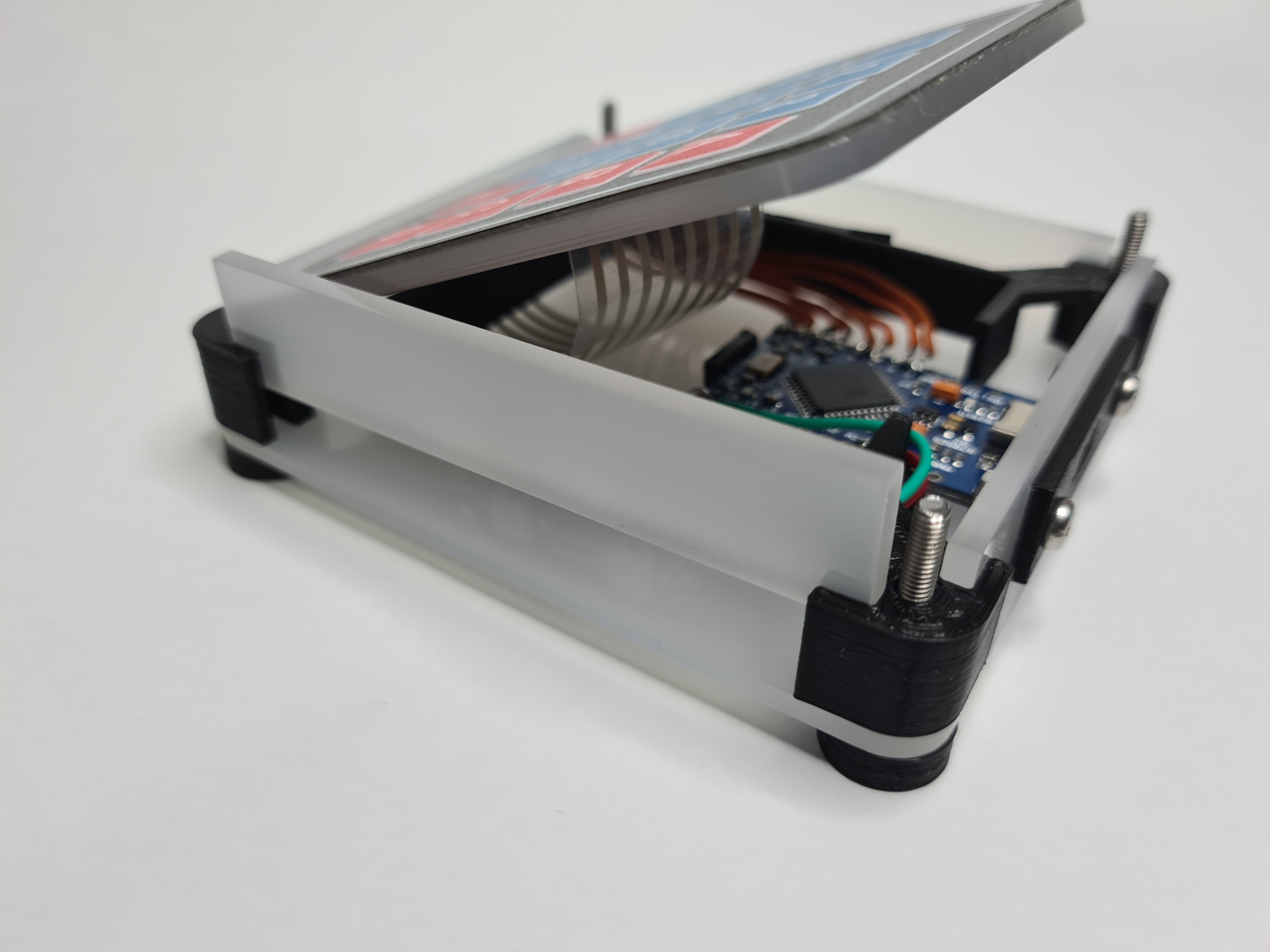
The case consists of 4 acrylic walls, connected at the corners with 3d printed pieces, and sandwiched between 2 acrylic plates. The keypad rests on platforms on the corner pieces and is held down by the top plate. I plan to use M3x25 screws to connect everything together. With this sketch, I started to 3D model the case
3D modelling
Version 1
The differences between the sketch and this first version is the addition of the mount for the microcontroller and that the feet has not been modeled yet. However, after modelling it I realised that I did not have any place to mount the neopixel strips I planned to use.
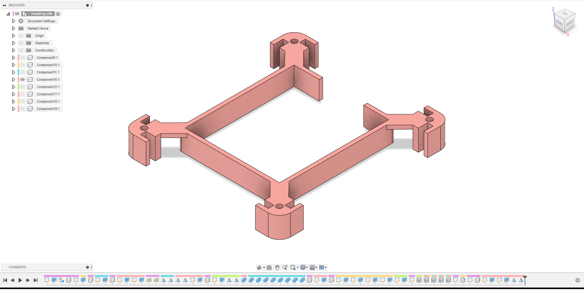
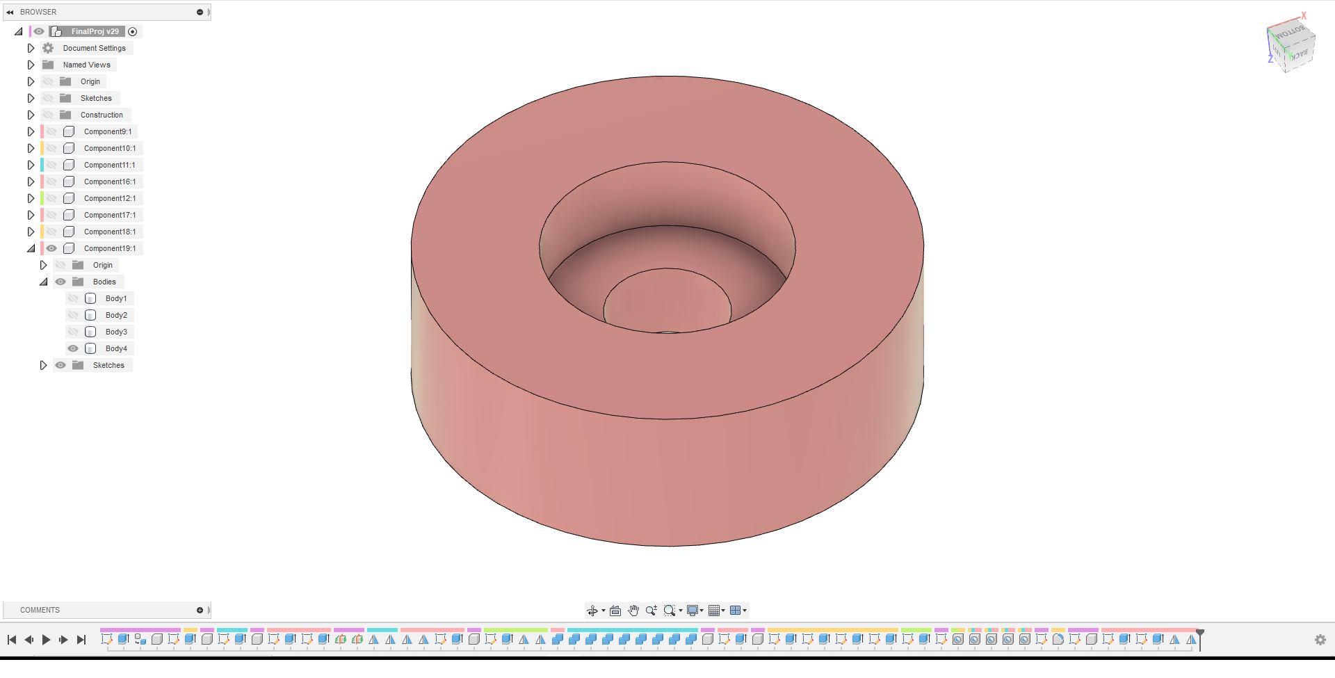
Version 2
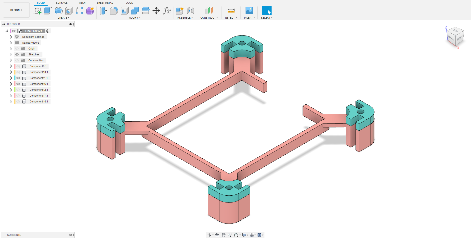
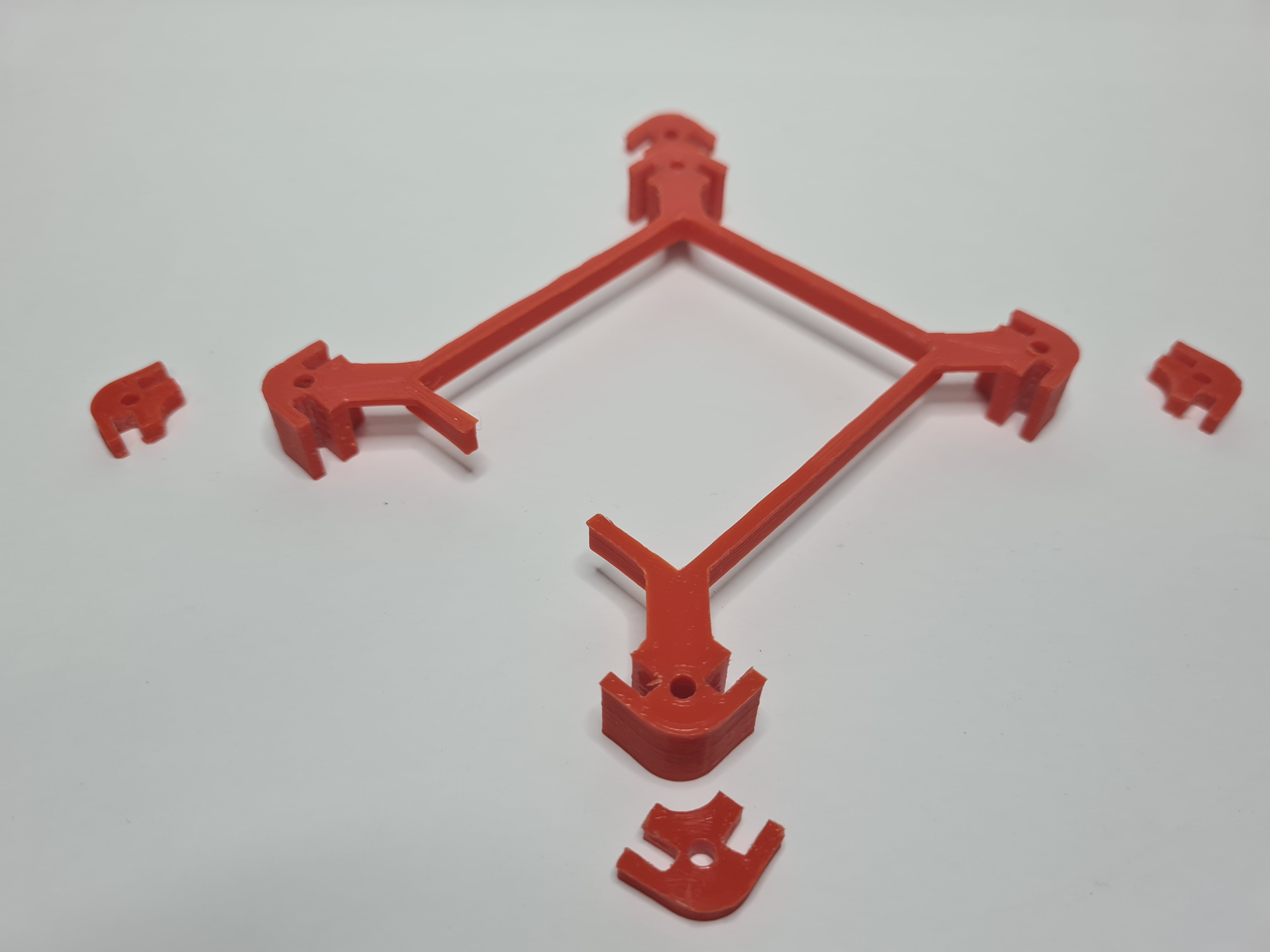
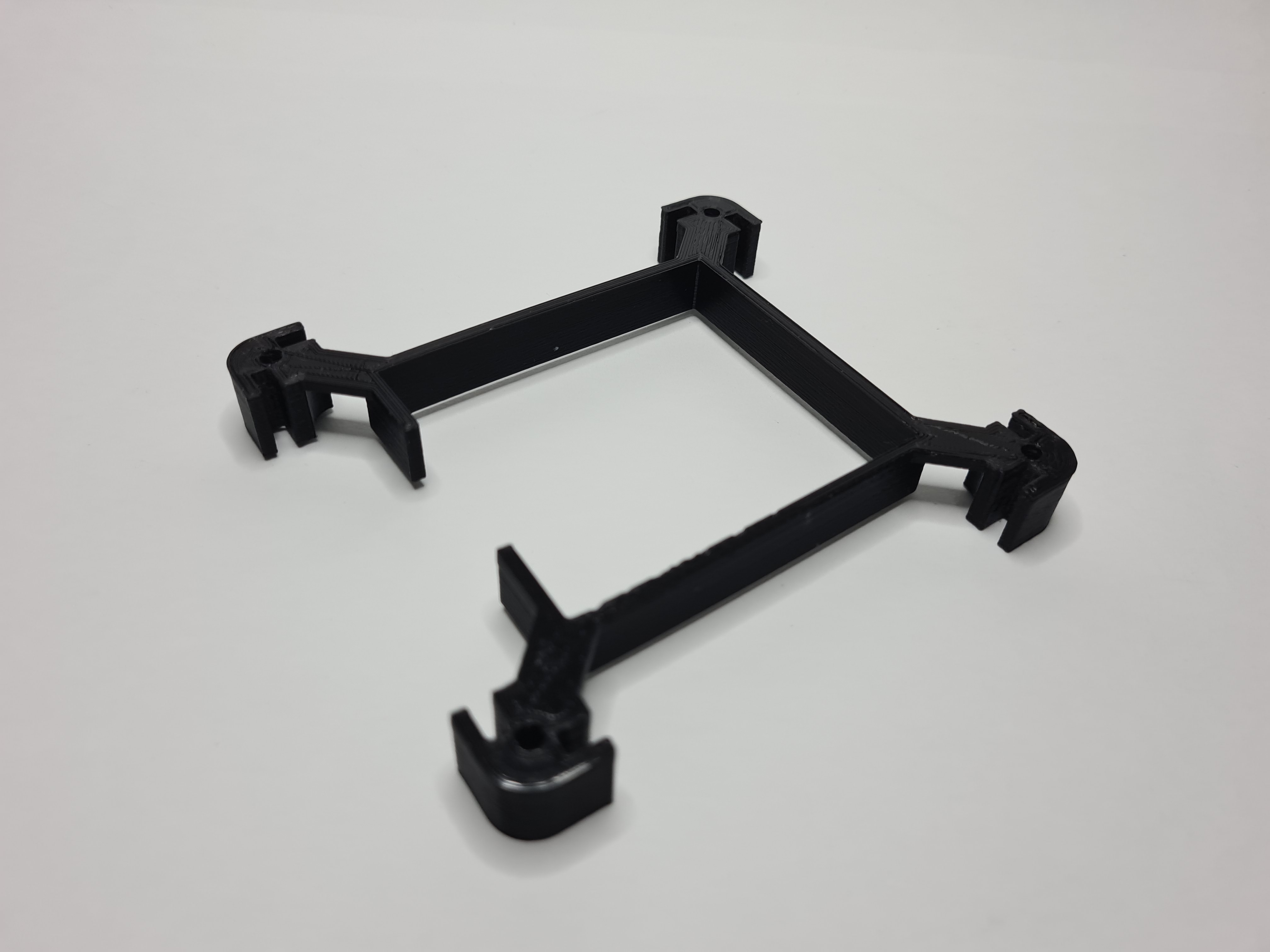
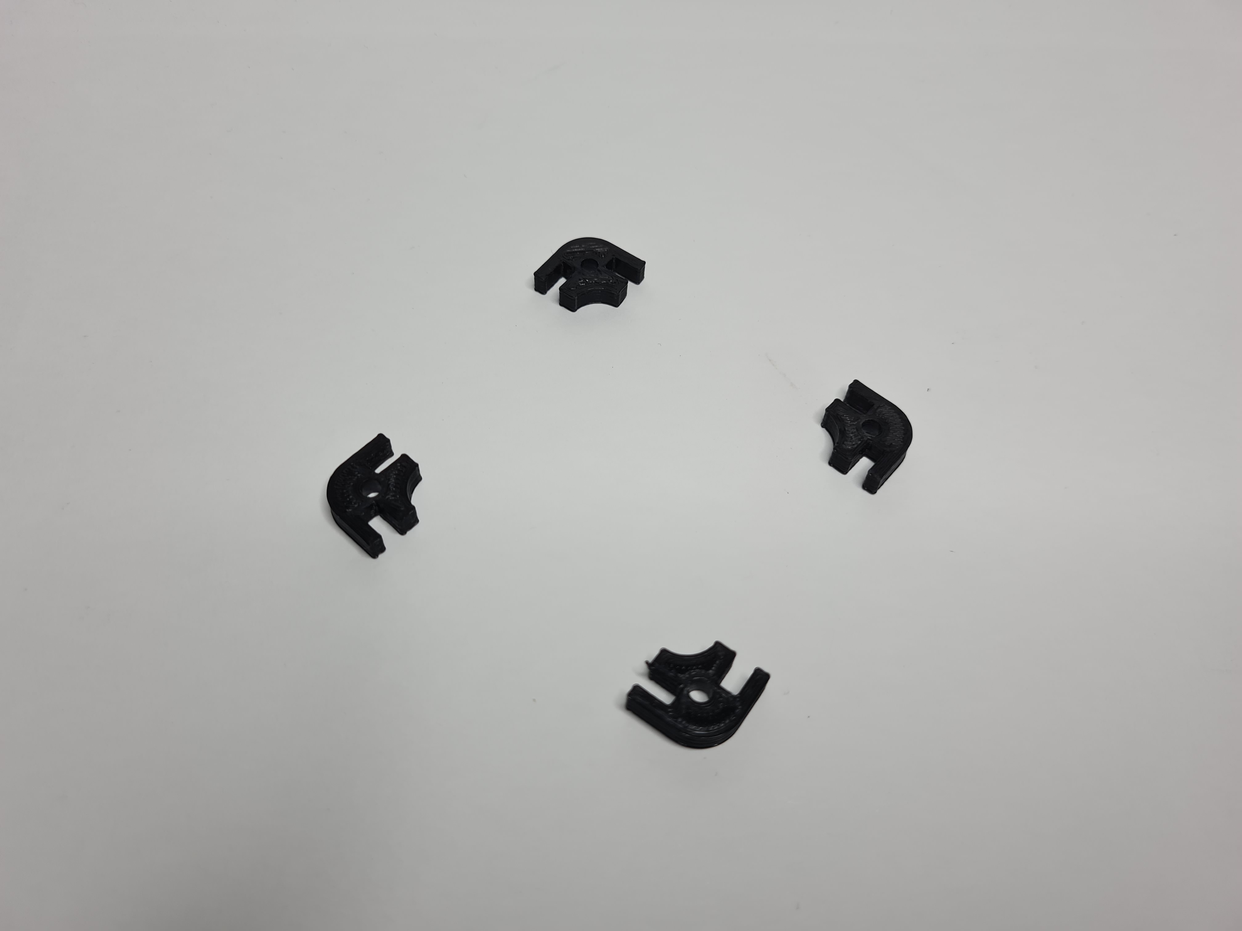
Changes were made to the corner pieces such that now there is a "floating" panel in the middle where the neopixels can stick onto. The keypad will still rest on the top of it. Originally, the turqoise and pink parts (pictured below) were a single body, but I separated them so that there will be no supports during 3D printing.
Another change made was adding more space for the keypad. The keypad is very thin and floppy on its own so I plan to stick it onto a laser cut panel in order to give it more rigitidy and strength. The thickness of the acrylic plate was accounted for in the space between the top plate and the place where it will rest.
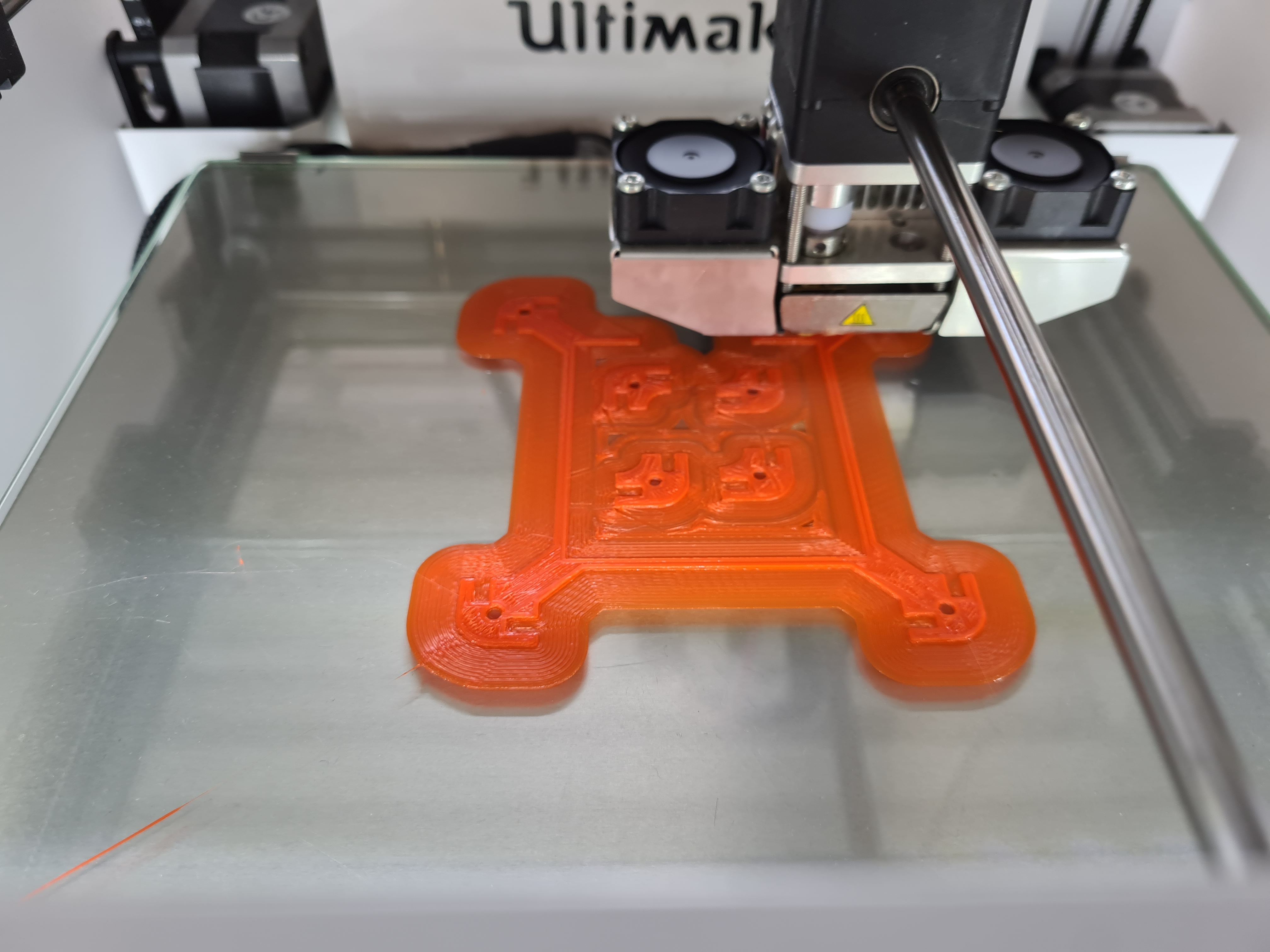
3D printing and laser cutting
Machine and settings used for 3D printing
| Machine | Ultimaker 2+ |
| Material | Orange PLA |
| Layer Height | 0.2mm |
| Infill Density and Pattern | 20% Grid |
| Printing speed | 80mm/s |
| Supports | None |
| Build Plate Adhesion | Brim |
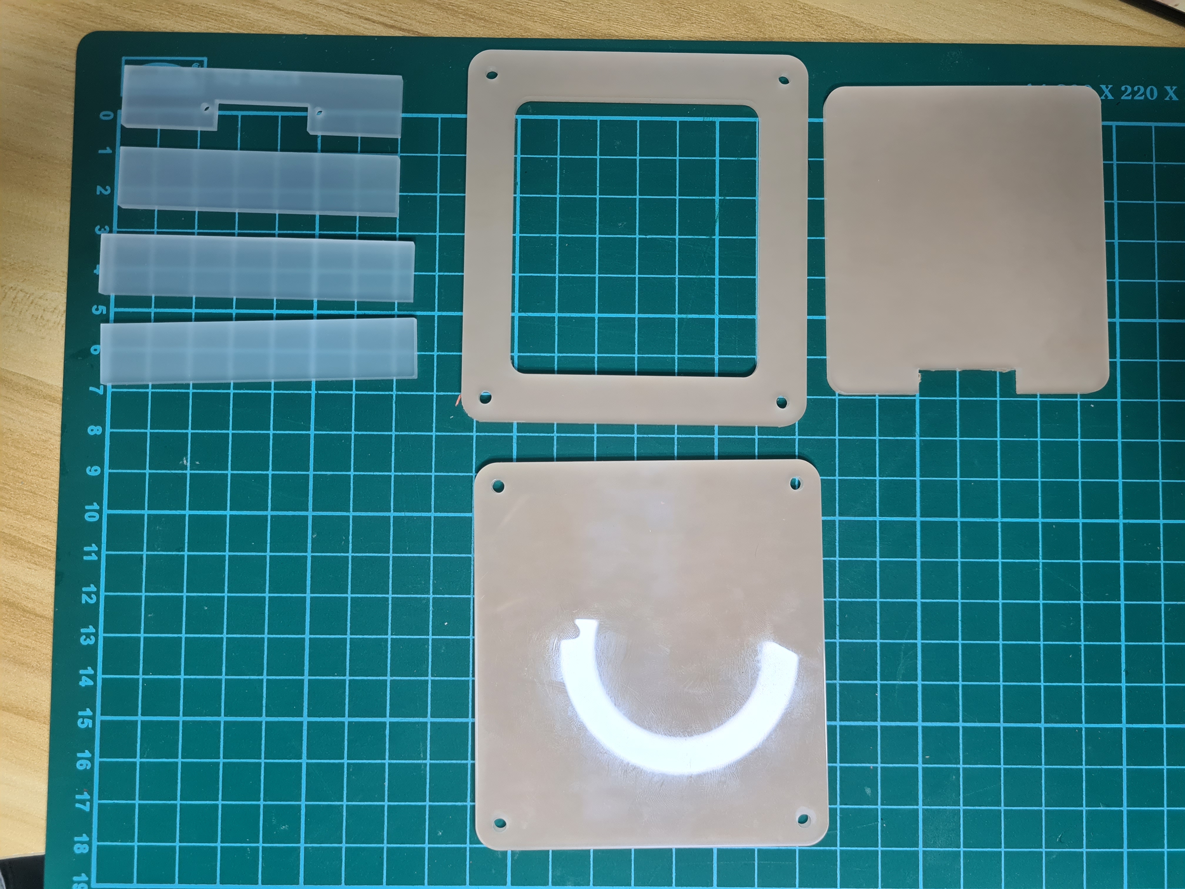
Machine and settings used for Lasercutting.
| Machine | Epilog Fusion Pro |
| Material Thickness and Type | 3mm Frosted Acrylic |
| Cut Settings | Speed - 18 |
| Power - 90 | |
| Frequency - 90 | |
| Engrave Settings | None |
Issues
After I got all the parts, I faced 3 issues.
Issue 1: I did not properly measure how wide the neopixel strips were before printing. The current width on the 3D model was 5mm, but the neopixels are 9~10mm wide. With the current model, only half of the width would be secured.
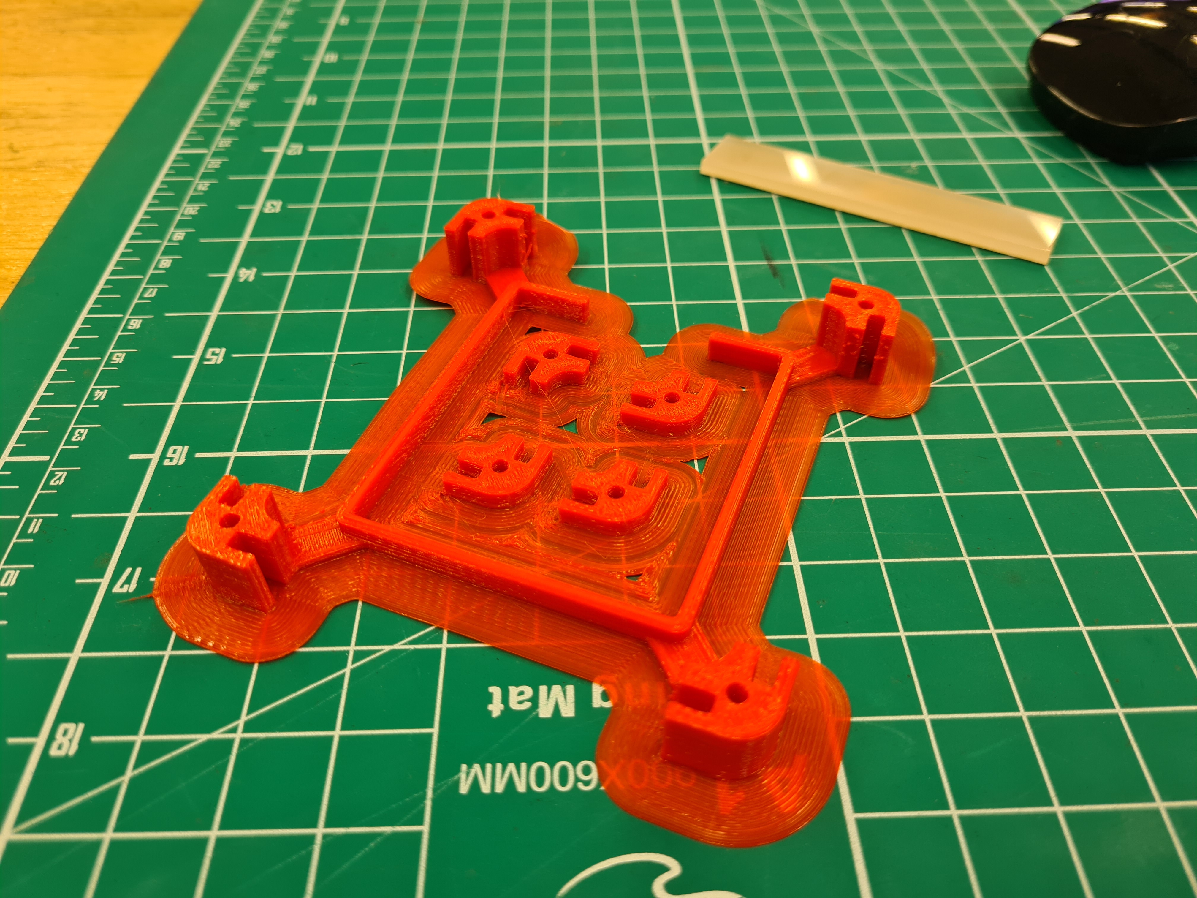
Issue 2: Using the brim was a mistake. Because the parts being printed were totally flat with relatively large surface area, I could have gotten away with printing without the brim. However, I still did, which resulted in lots of time being spent cleaning up the print, as the brim got into all the slots for the acrylic plate.
Issue 3: I did not account for tolerances and shrinkage during the print. As a result, the acrylic plates could not fit into their slots and lots of post processing work had to be done to make sure they fit. Moreover, the holes I modelled to be M3 ended up shrinking as well, requiring me to drill it out again using a 3mm drill.
Even with all these issues, I still sanded all the parts to make it fit in order to see how everything went together.
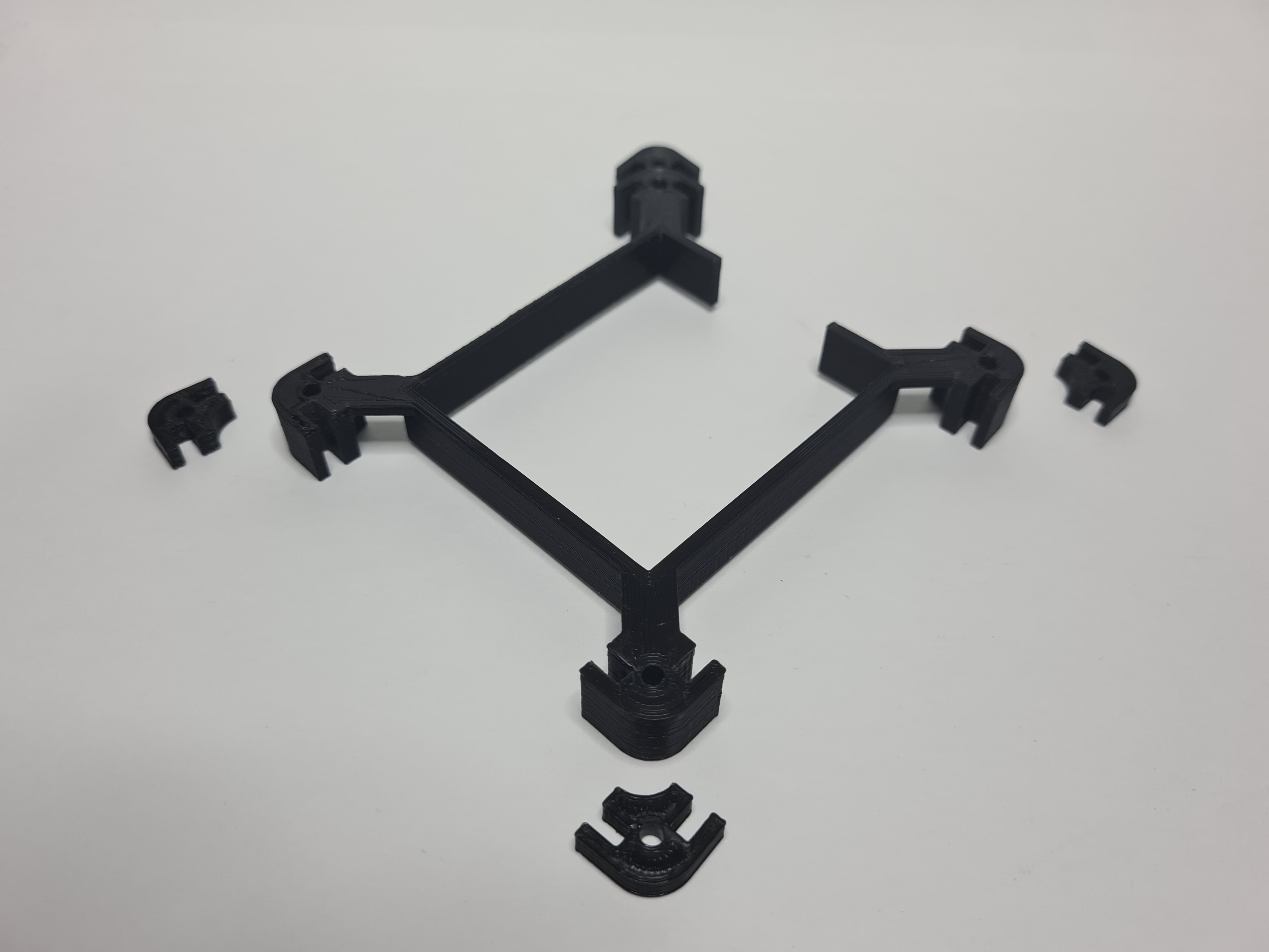
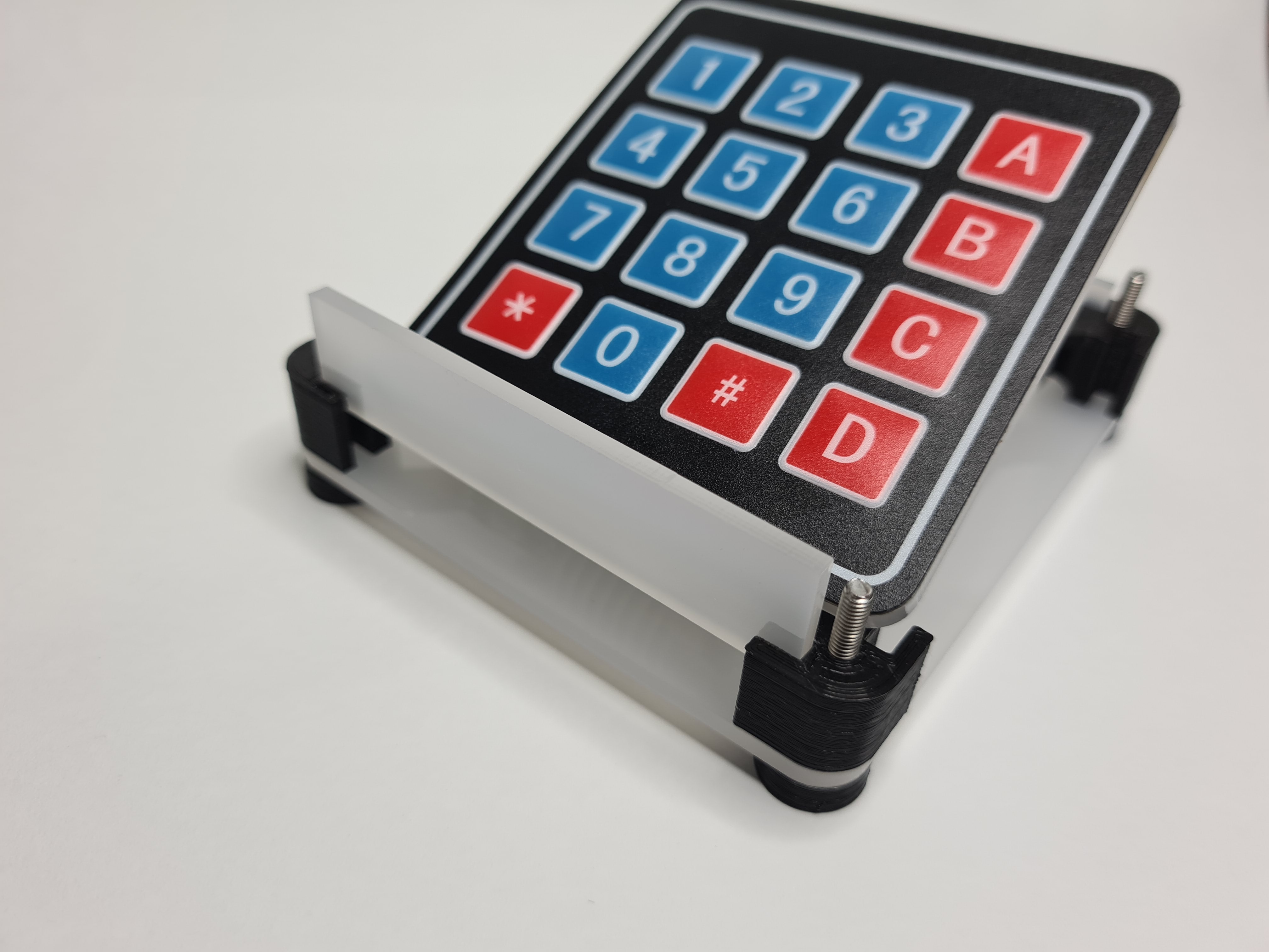
Week 1 assembly
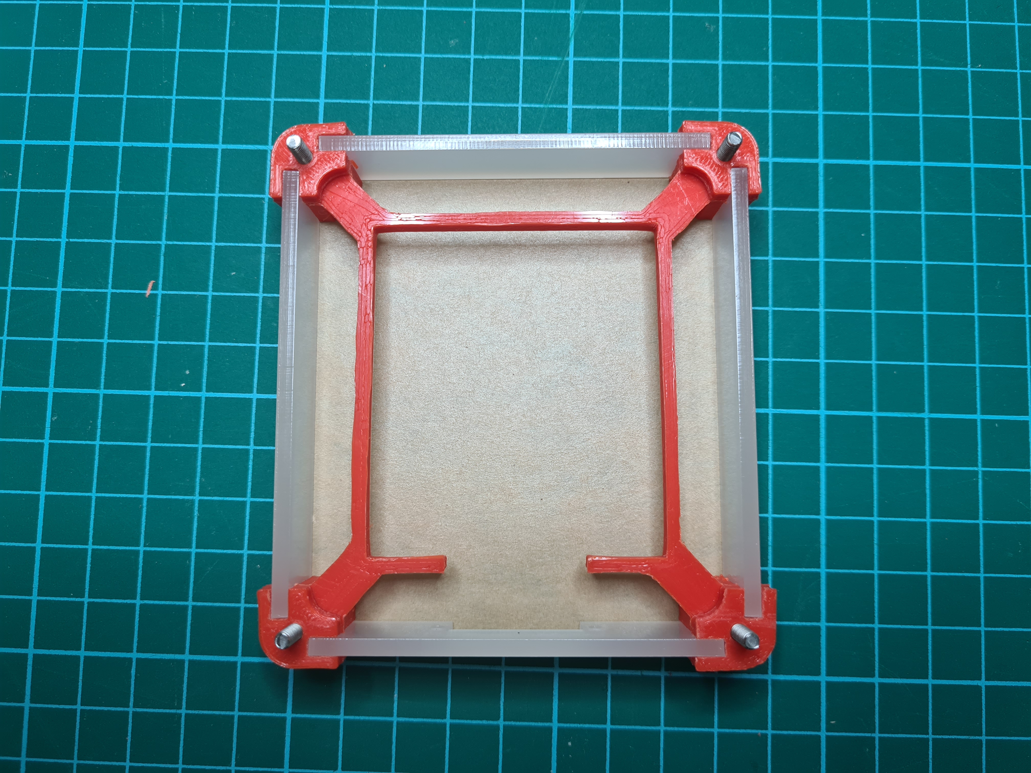
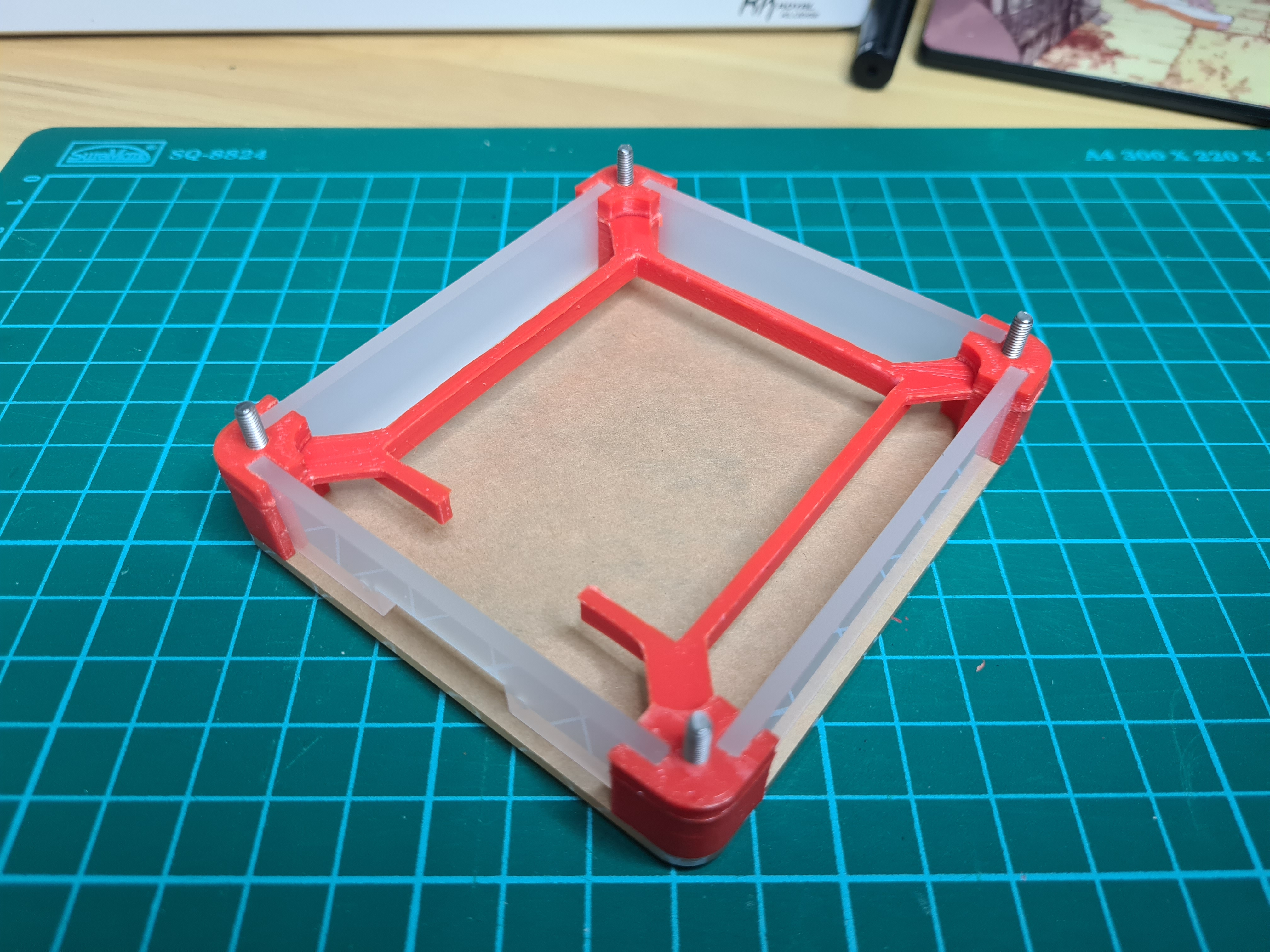
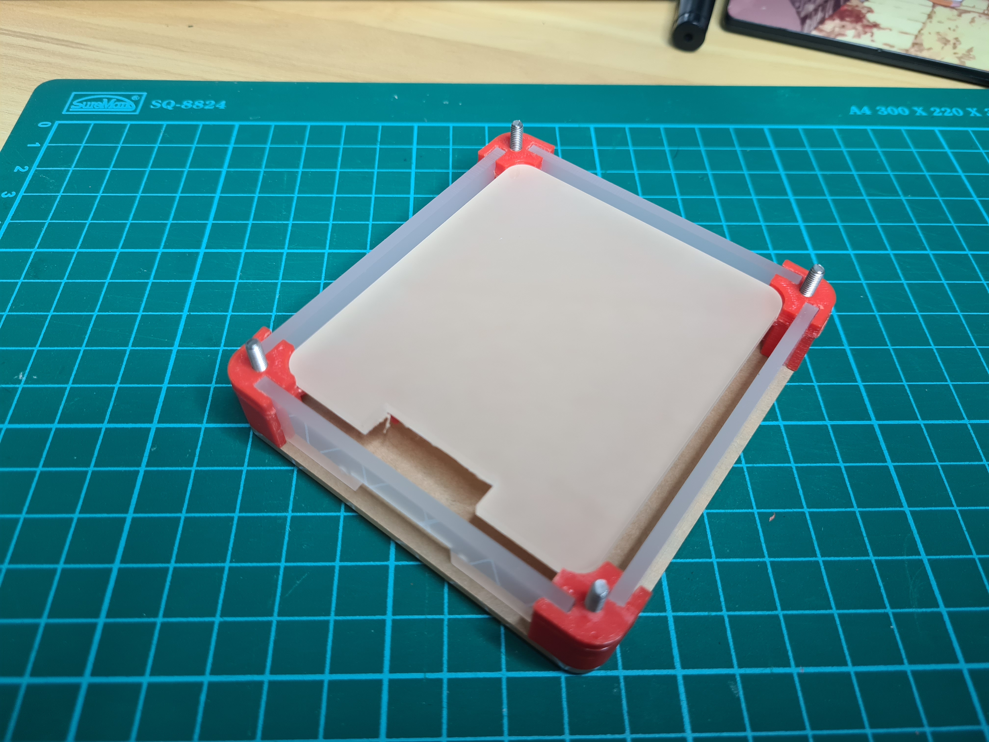
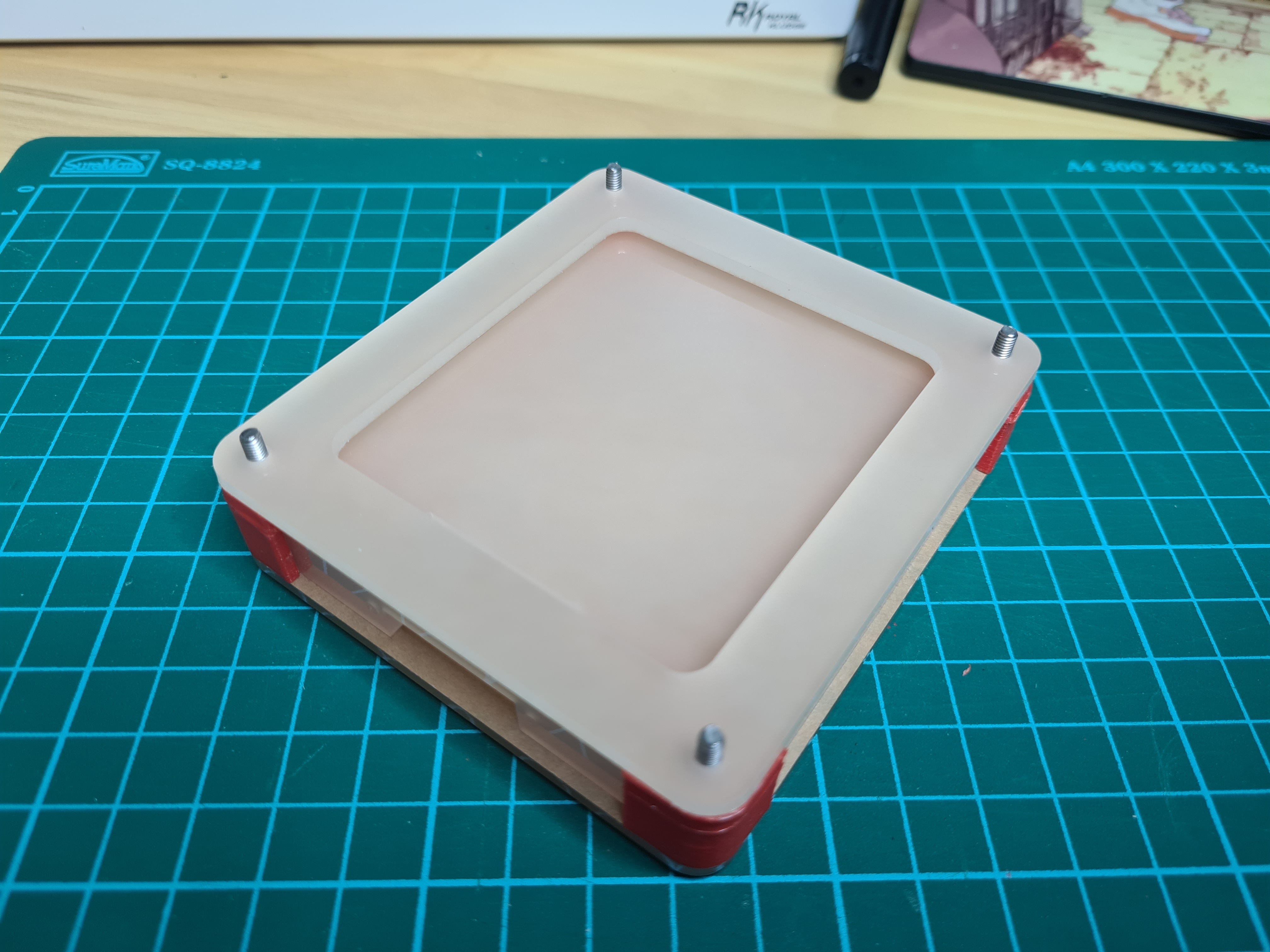
Next week, I plan to reprint the corner piece with the correct width for the neopixel, print out the mount for the microcontroller, as well as solder the keypad and neopixels to the microcontroller.
Week 2
From the first week, I just kept the laser cut parts as there were no changes done to the design. During this week, I plan to print out the remaining parts such as the arduino mount and the feet, remodel and reprint the corner pieces as well as finish soldering the electronics.
3D Modeling
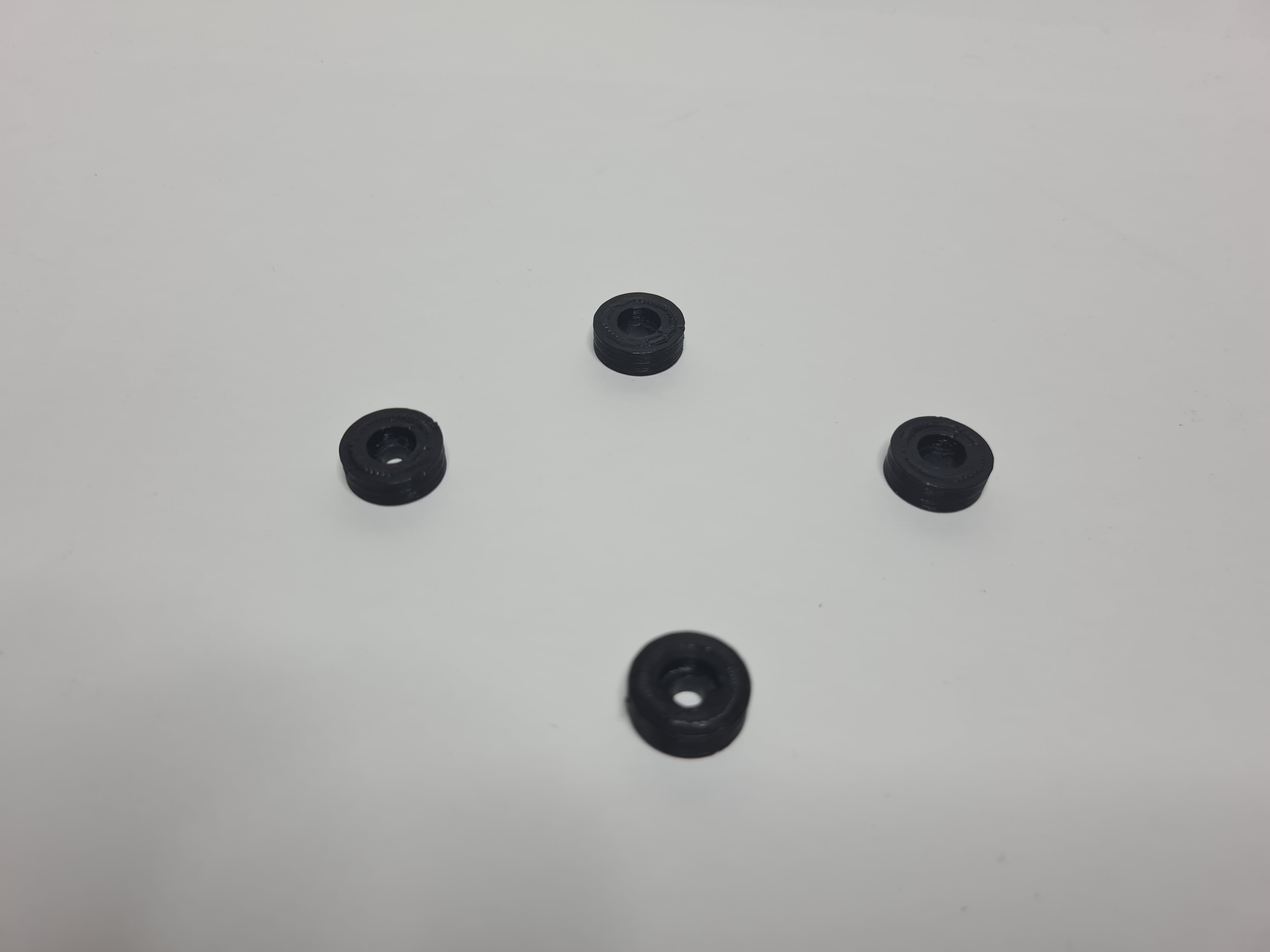
As stated in week 1, the original mounting place for the neopixel LED strips was too narrow. I extended the extrude downwards by an extra 5mm, and modelled the feet for the macropad. With this, the design is finalised.
3D printing
Machine and settings used for 3D printing
| Machine | Ultimaker 2+ |
| Material | Black PLA |
| Layer Height | 0.2mm |
| Infill Density and Pattern | 20% Grid |
| Print Speed | 80mm/s |
| Supports | None |
| Build Plate Adhesion | None |
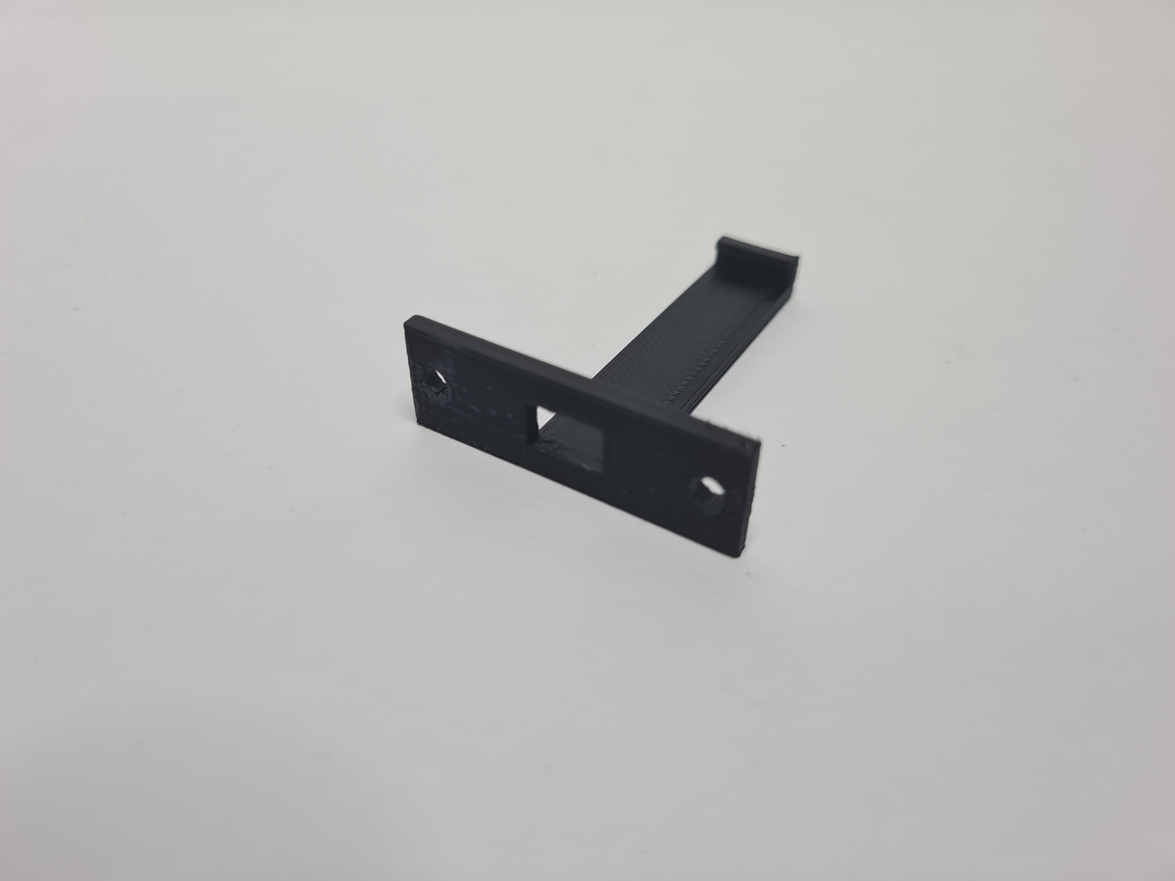
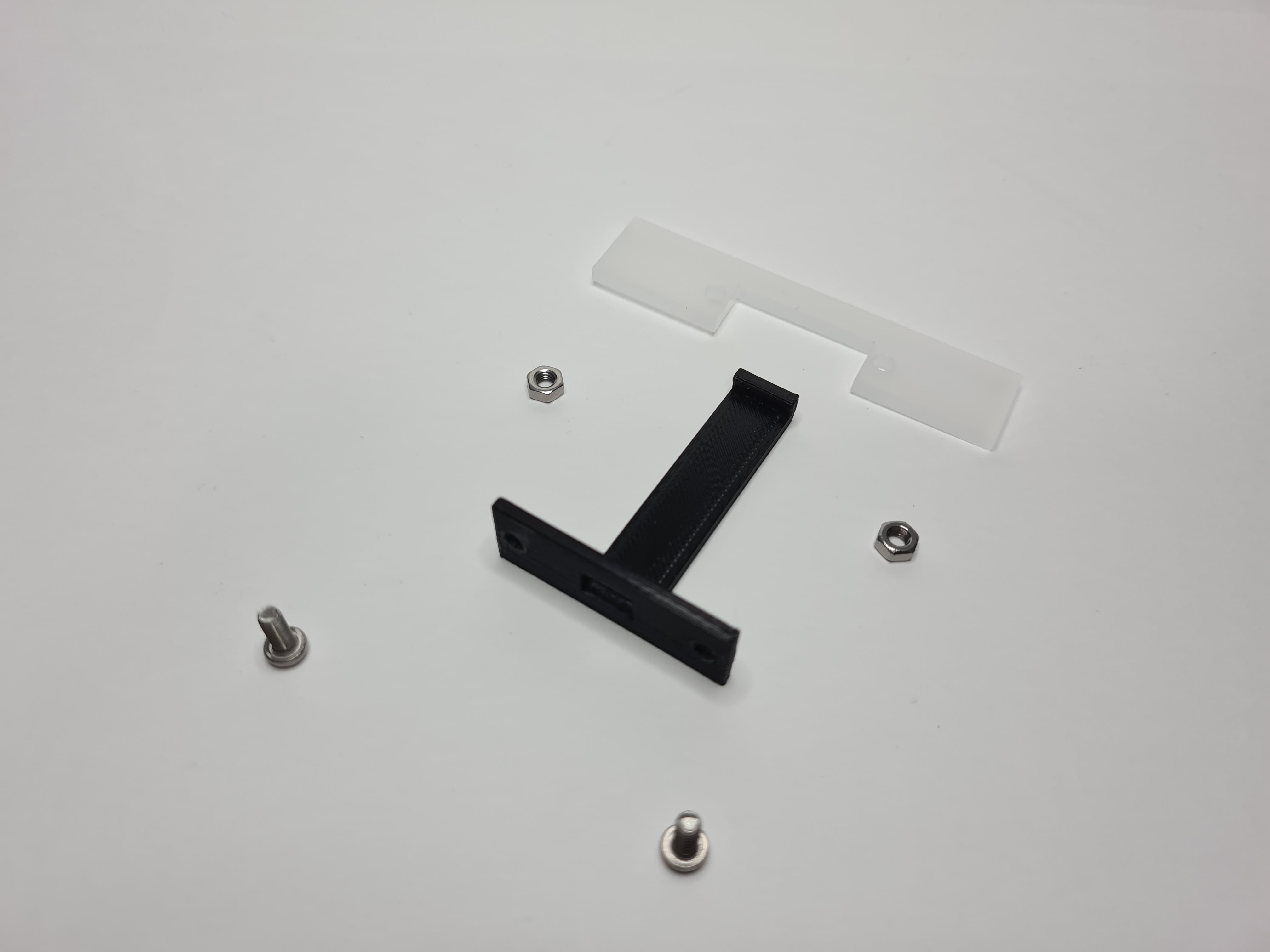
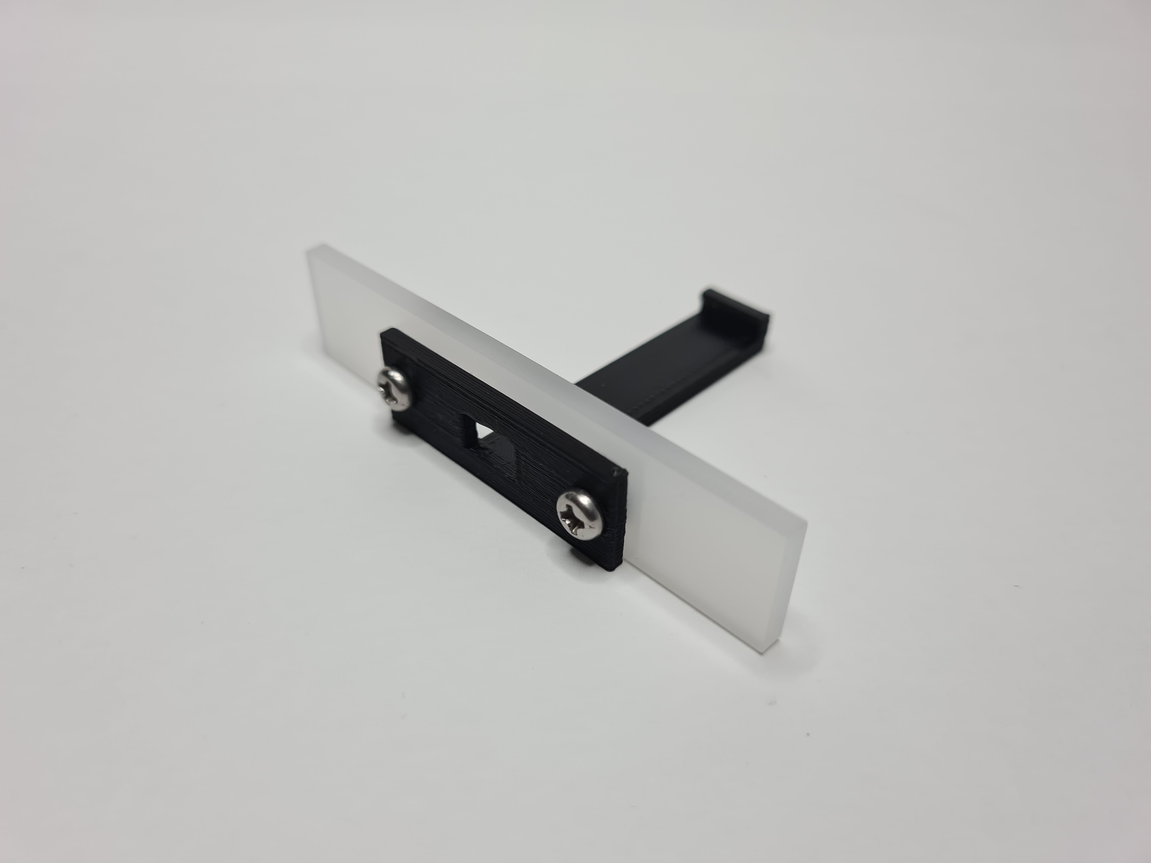
Even though the parts that the acrylic plate meshes into was not changed, somehow this print had better tolerences than the orange print. There was no sanding required to fit the acrylic side plates in. The 3mm hole still shrunk slightly and had to be drilled out. I printed the mount without supports as it was not really an area of importance and it came out fine, though just like the other holes, I had to drill the mounting holes out.
Now that the case has been made, time to move on to electronics.
Electronics
This whole project relies on an arduino pro micro board I had lying around. For this week, I just want to finish the soldering and make sure the components work before I start coding.
Wiring diagram
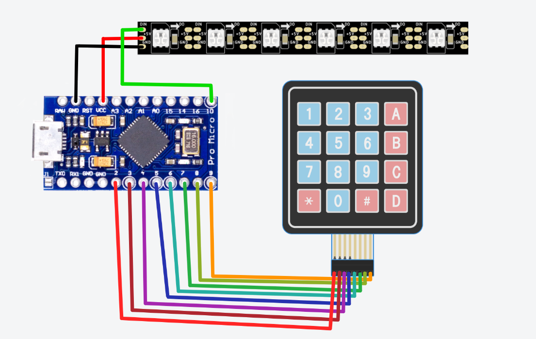
This was the first time I was soldering so at first, the solder job was not that good, but I gained a lot of experience during the whole process.
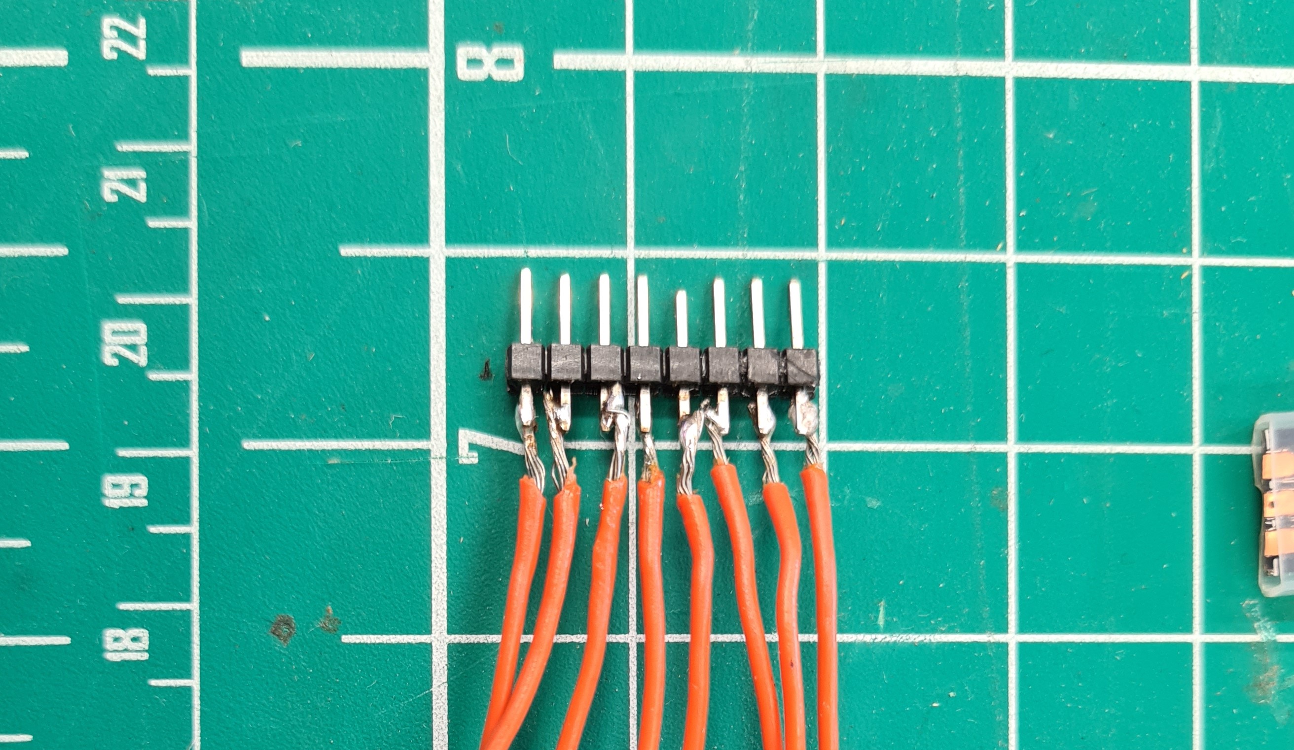
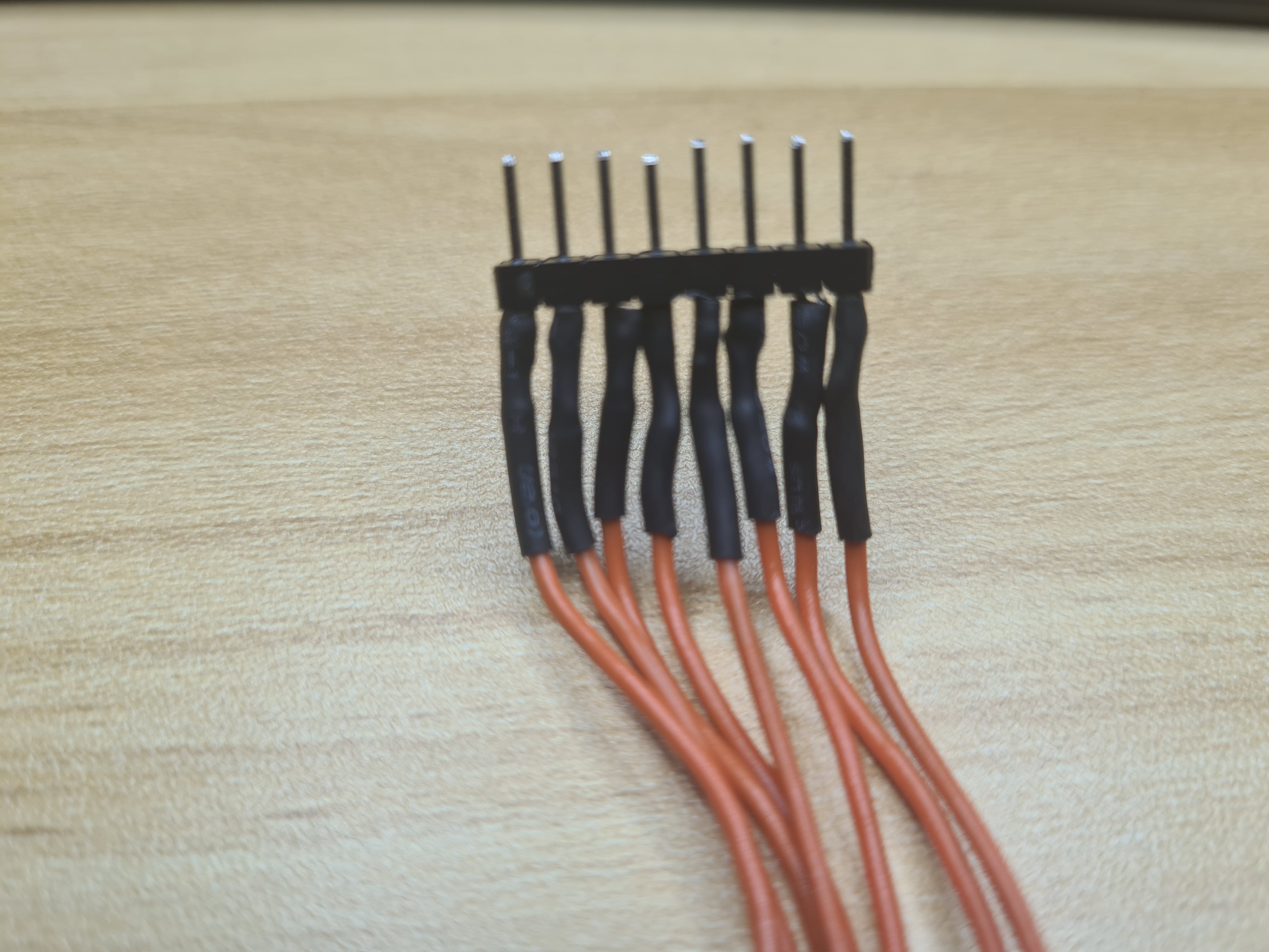
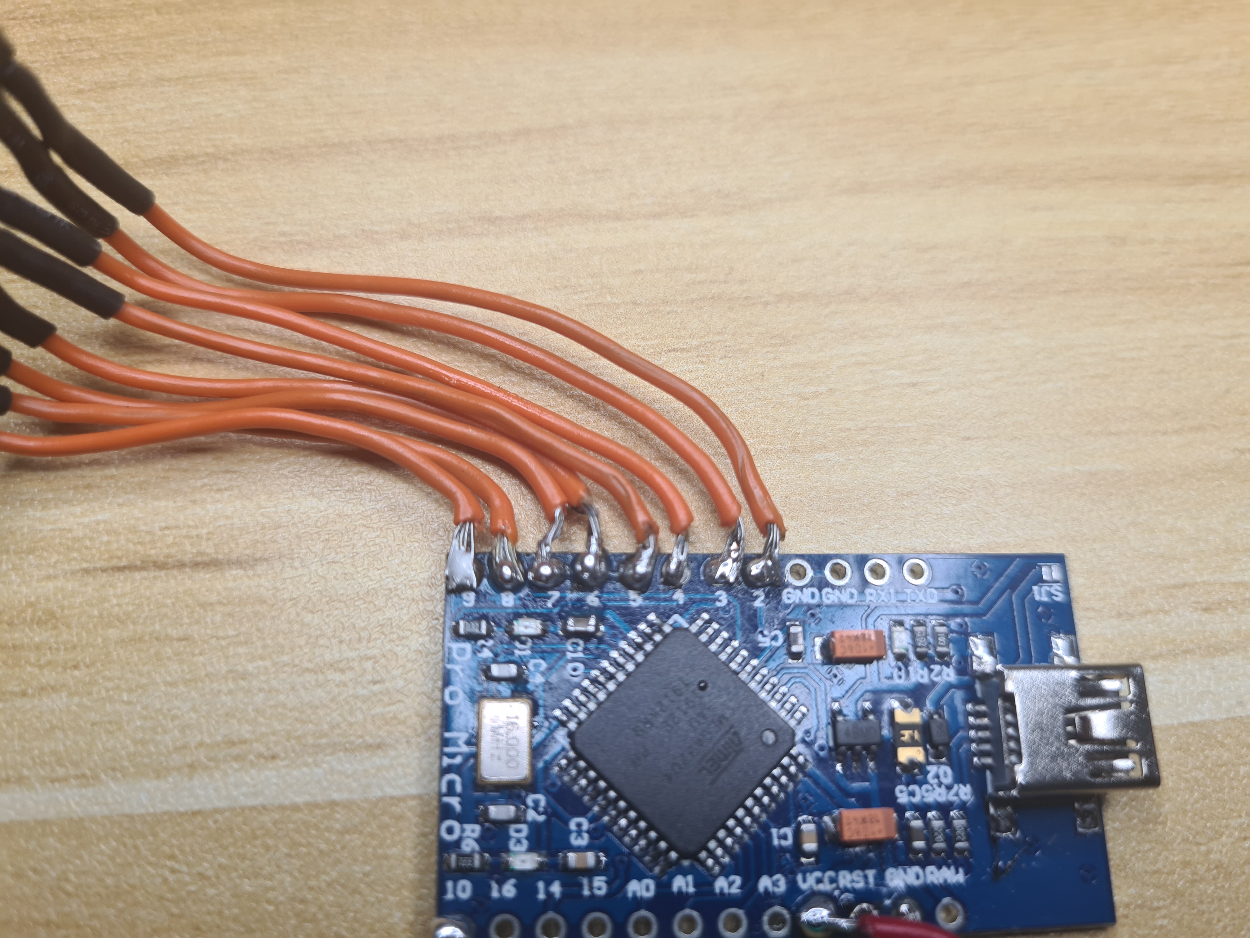
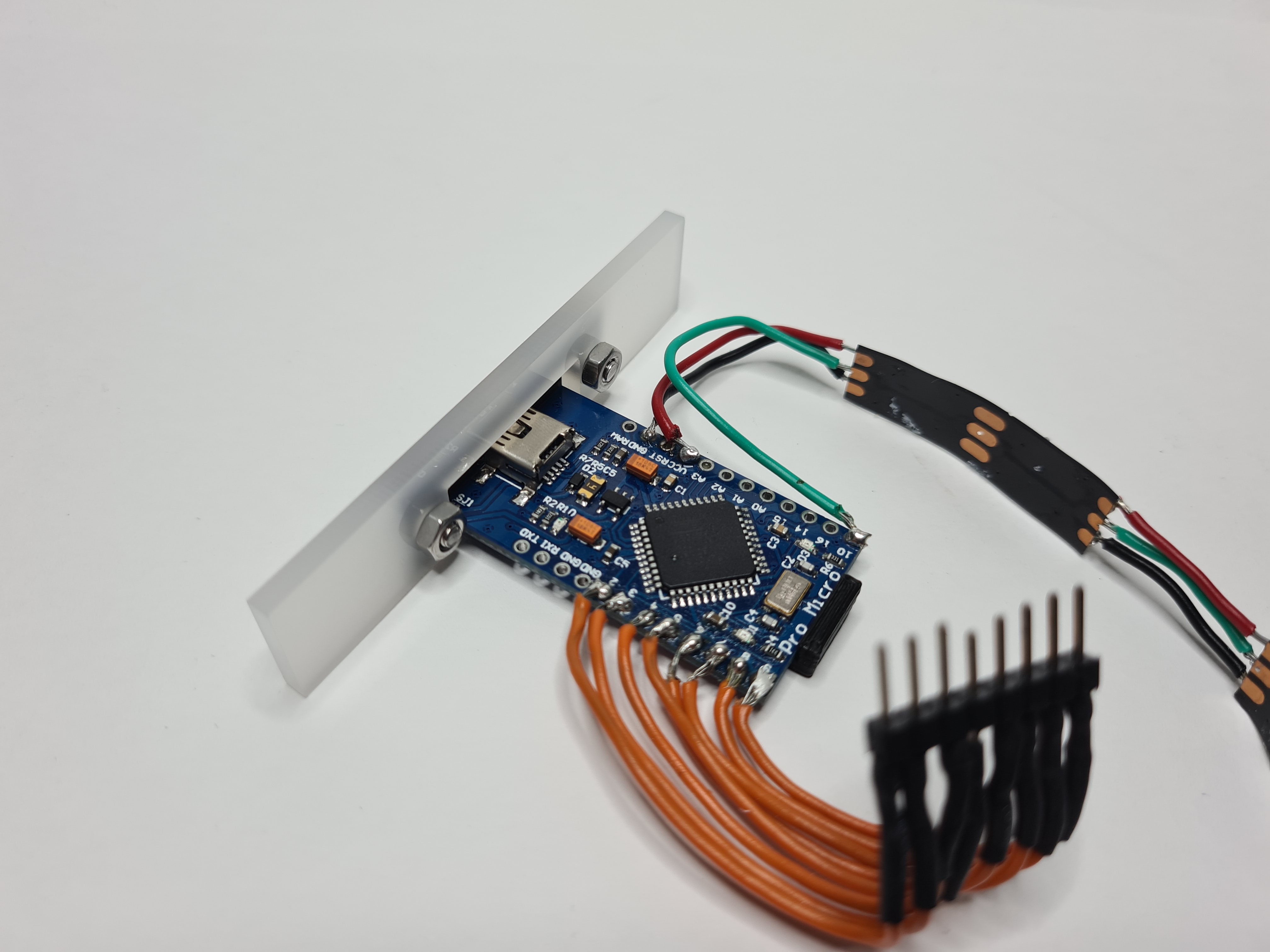
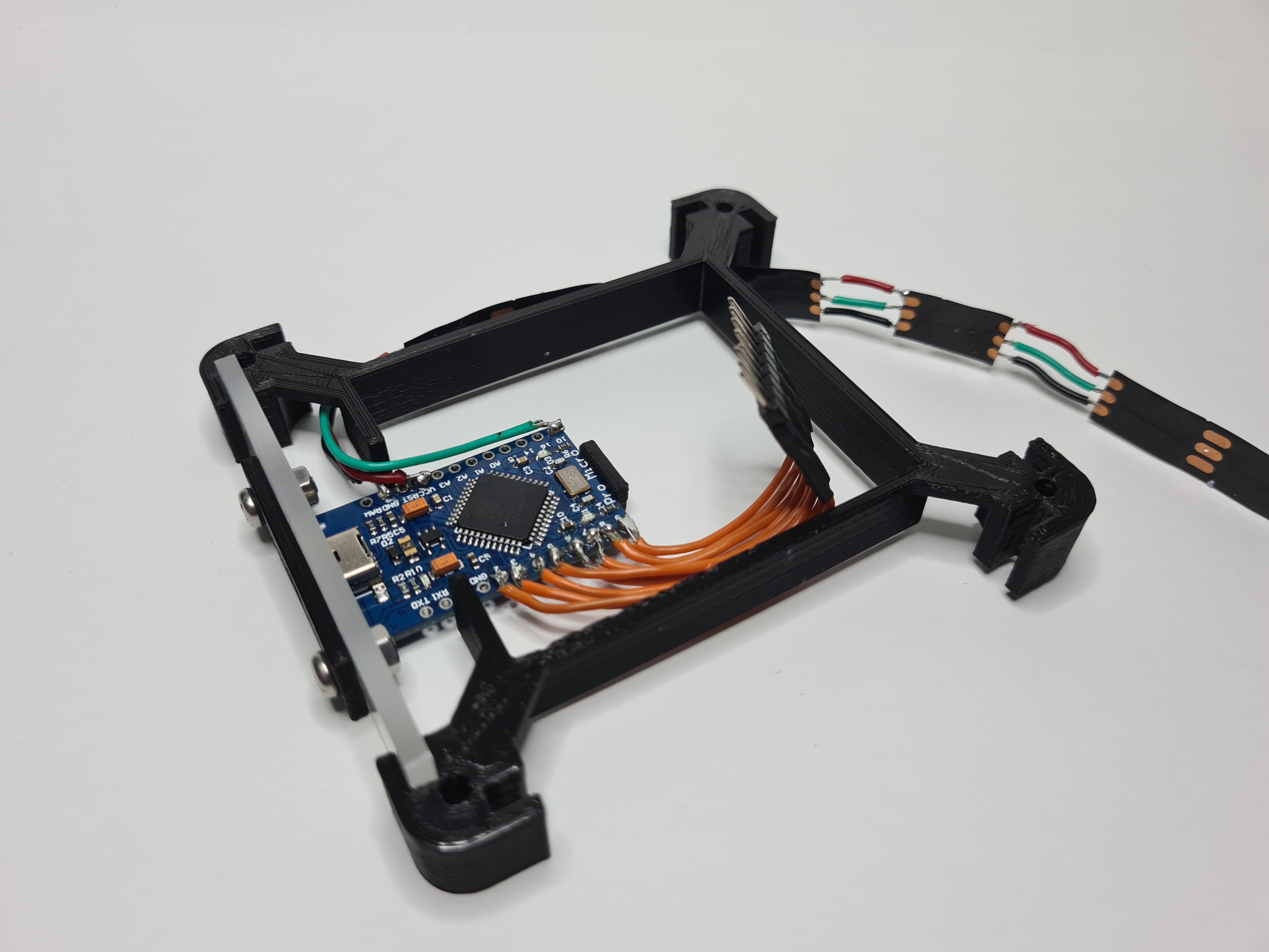
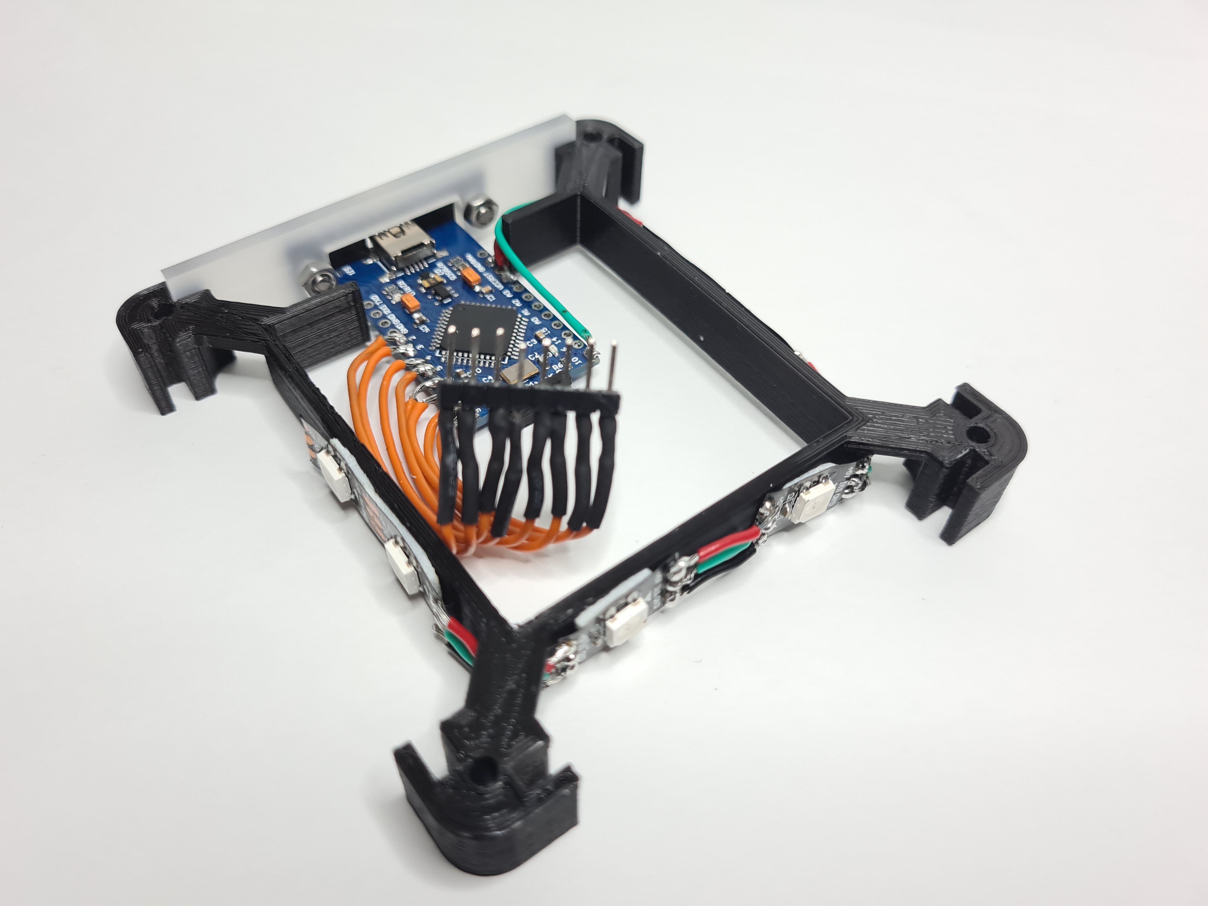
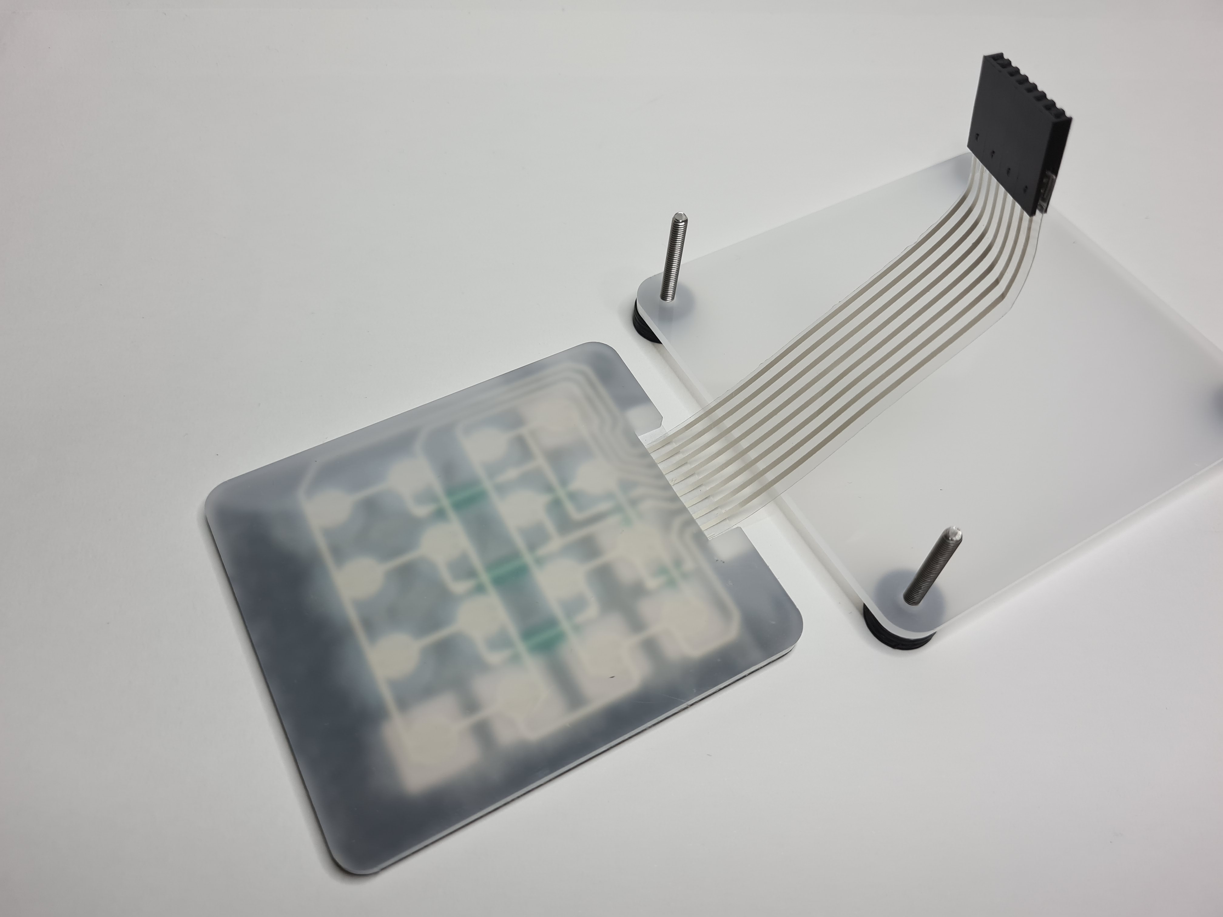
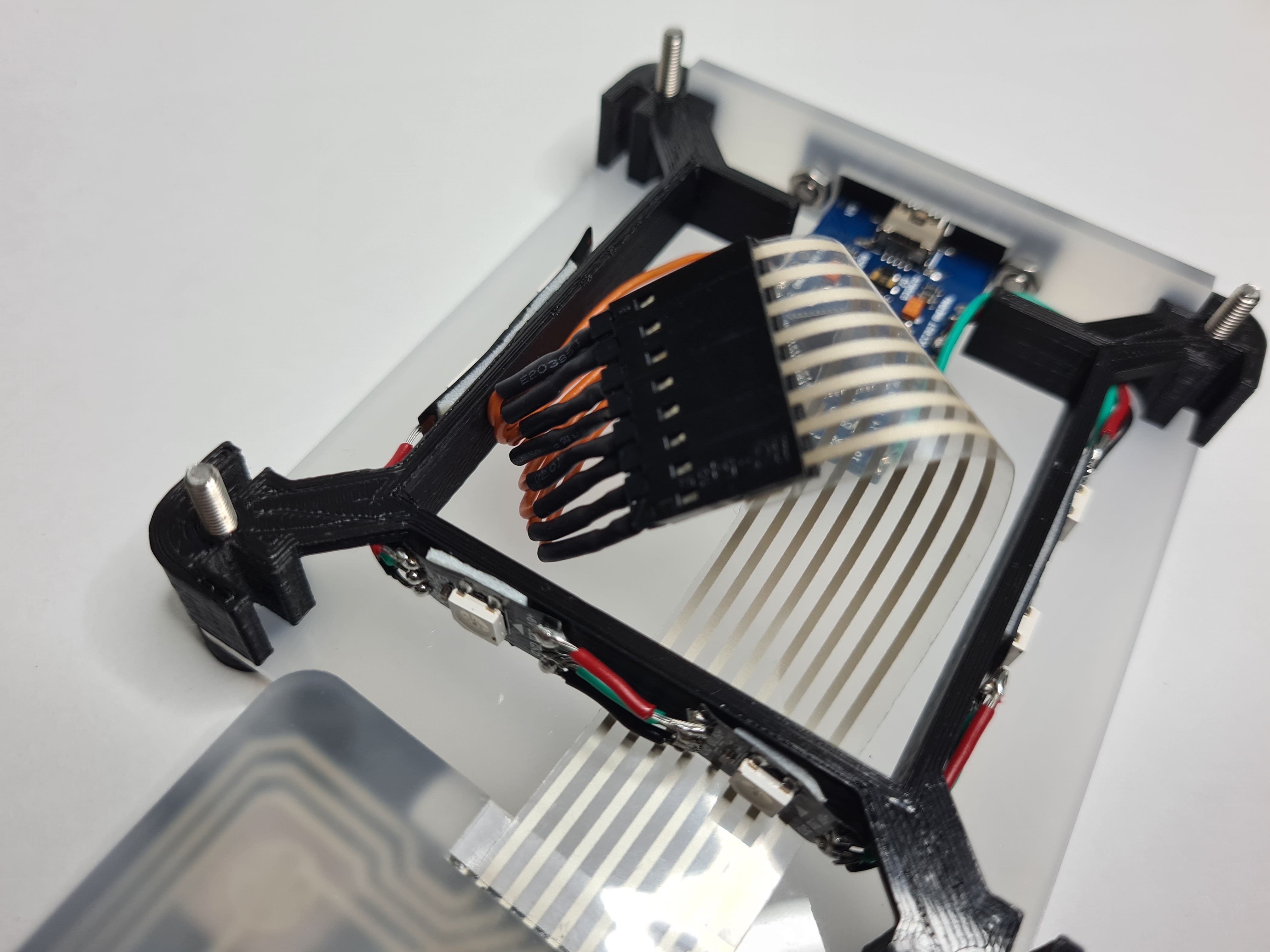
First was soldering the connections to the keypad. To make connecting to the keypad easier, wires were first soldered to 8 connected pin headers. Afterwards the pin headers can just plug into the keypad. These connections were the first ever soldering job I have done, and its clearly visible how shoddy it is. Nevertheless, instead of resoldering it, I just trusted that it will work and shrink-wrapped the connections, just in case there was a short between the wires. Afterwards, I soldered the other end of the wires to the arduino.
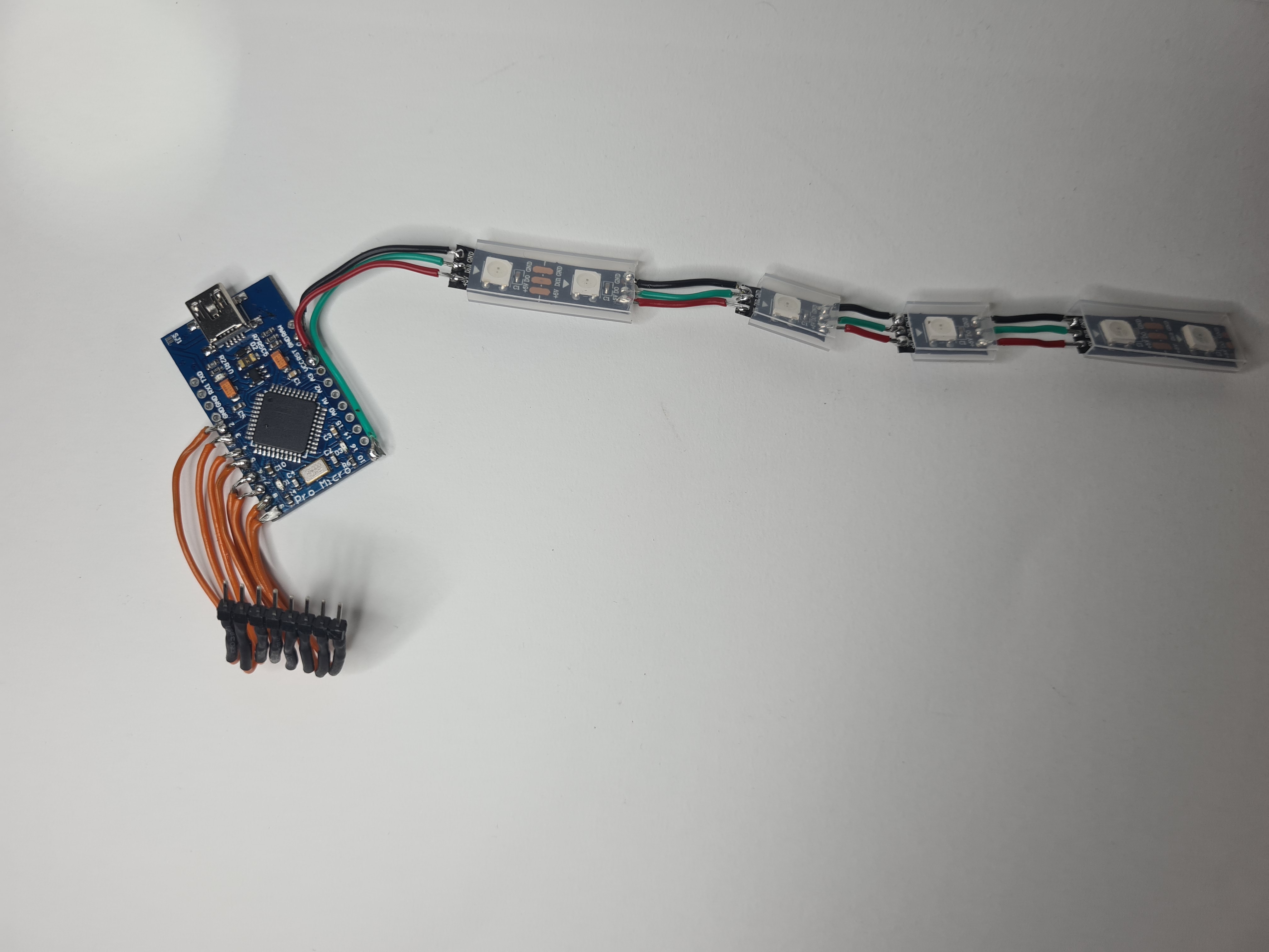
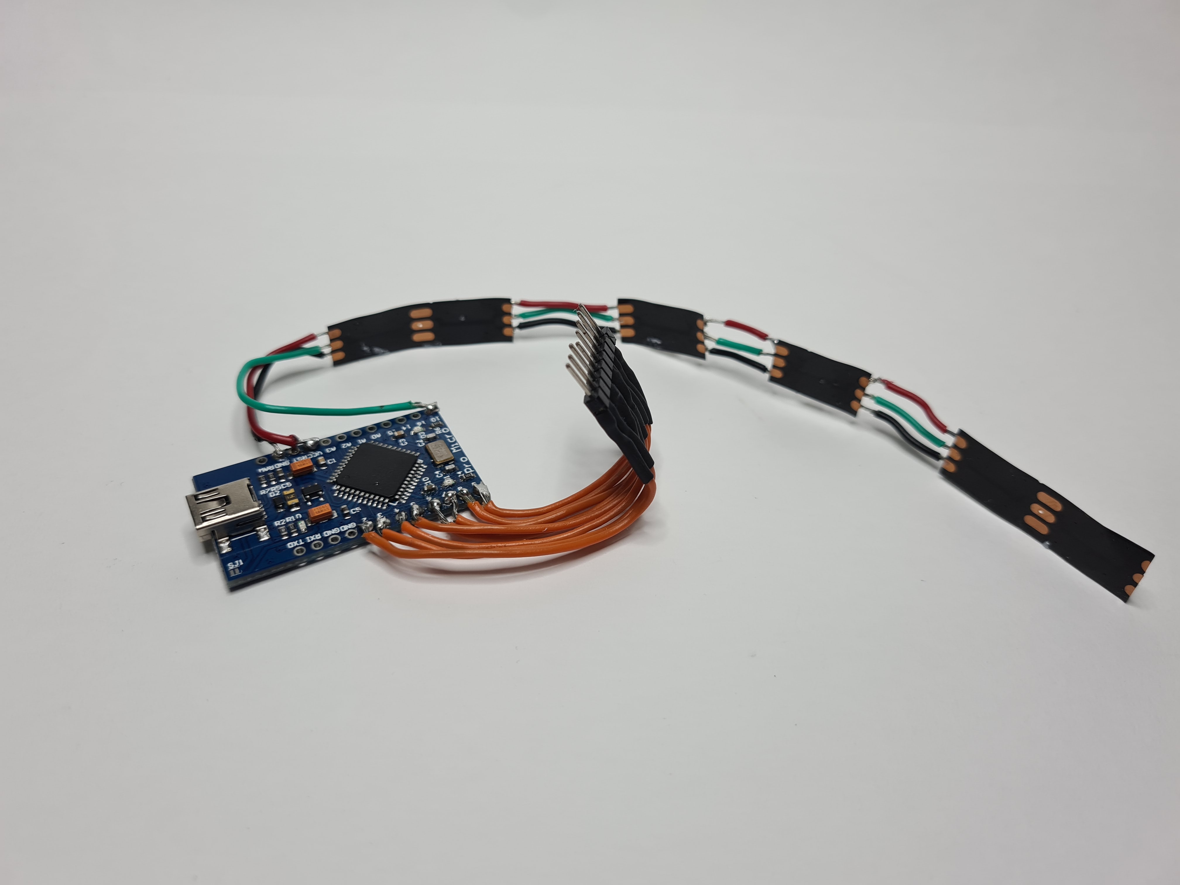
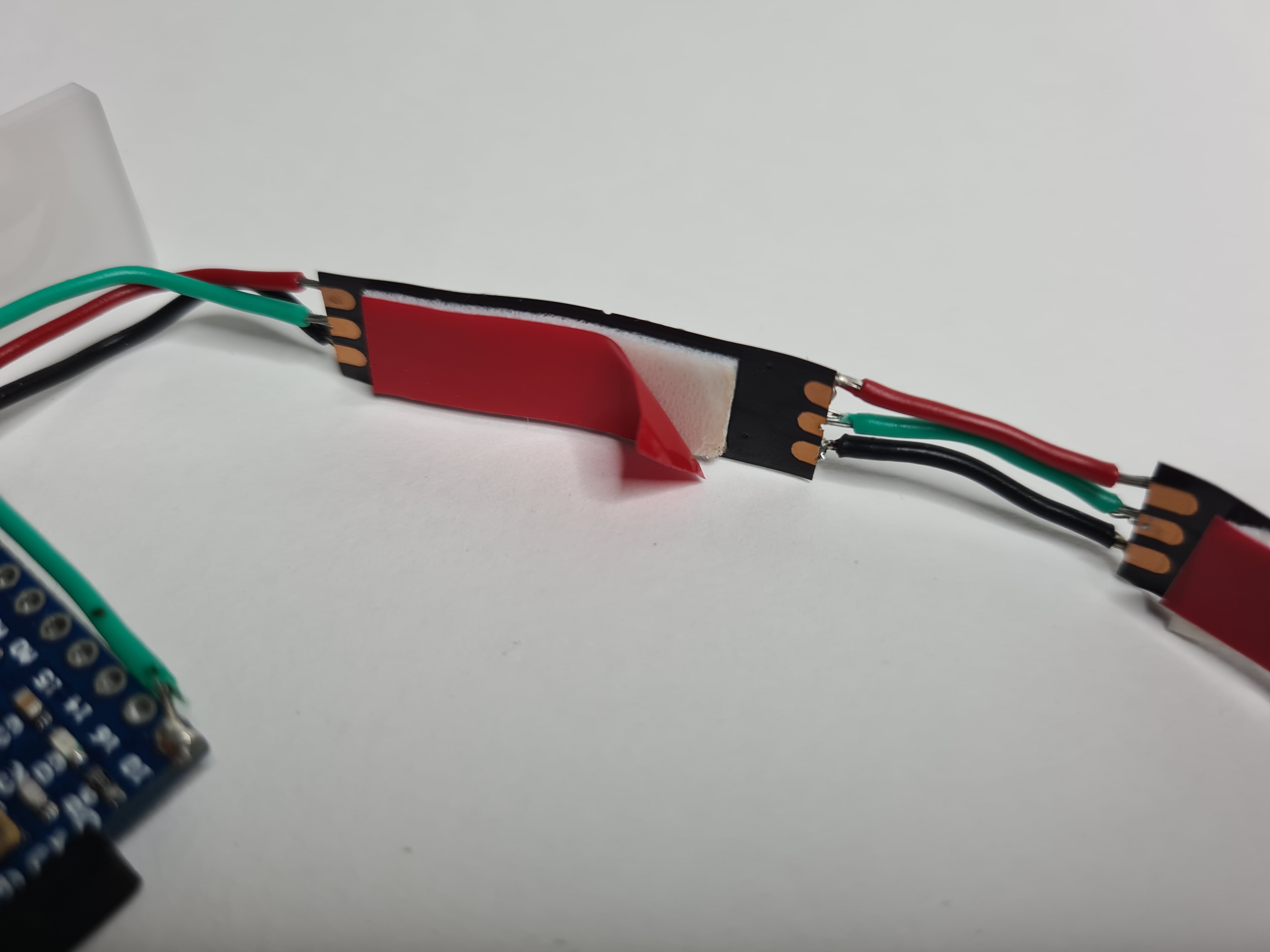
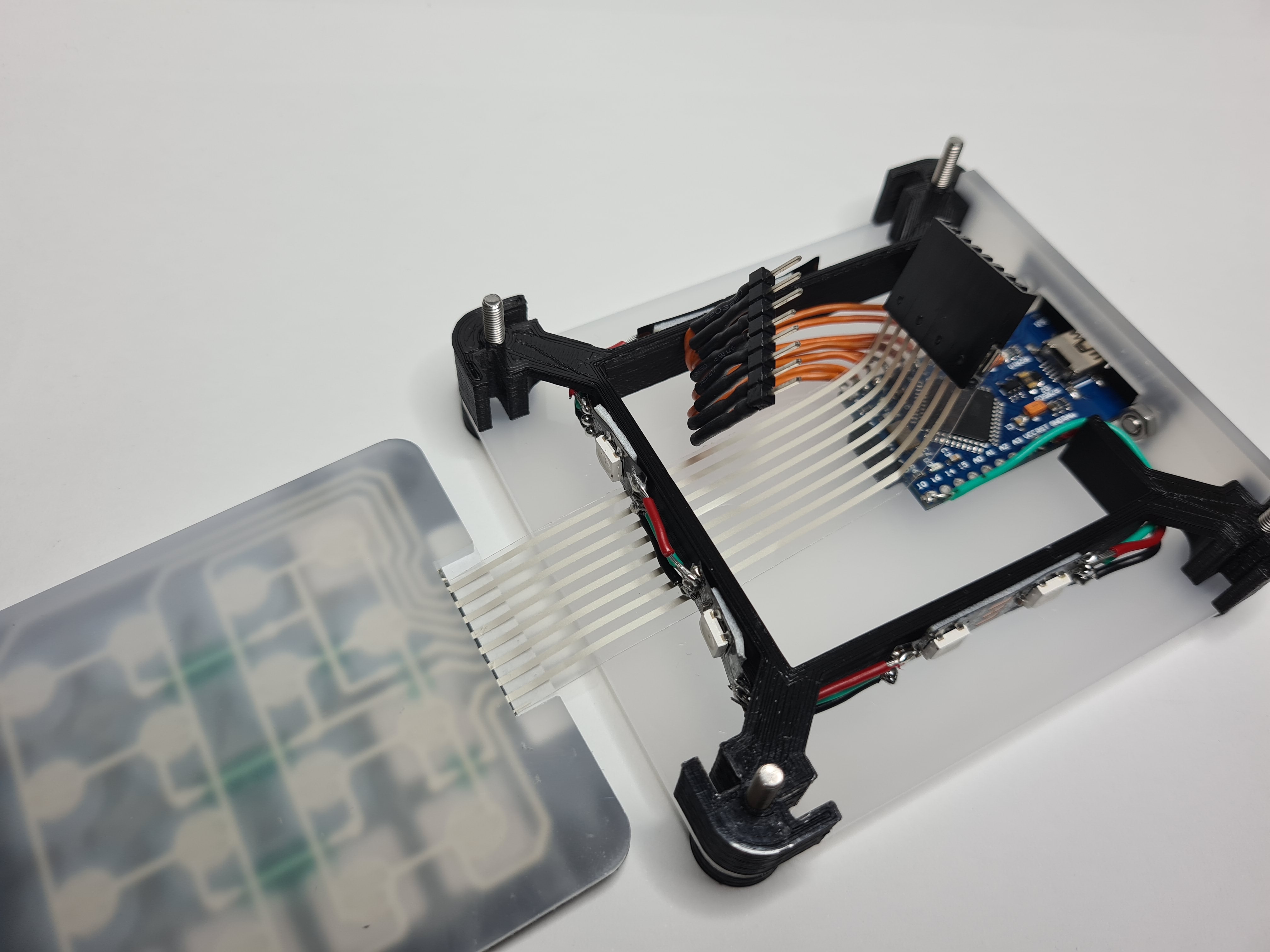
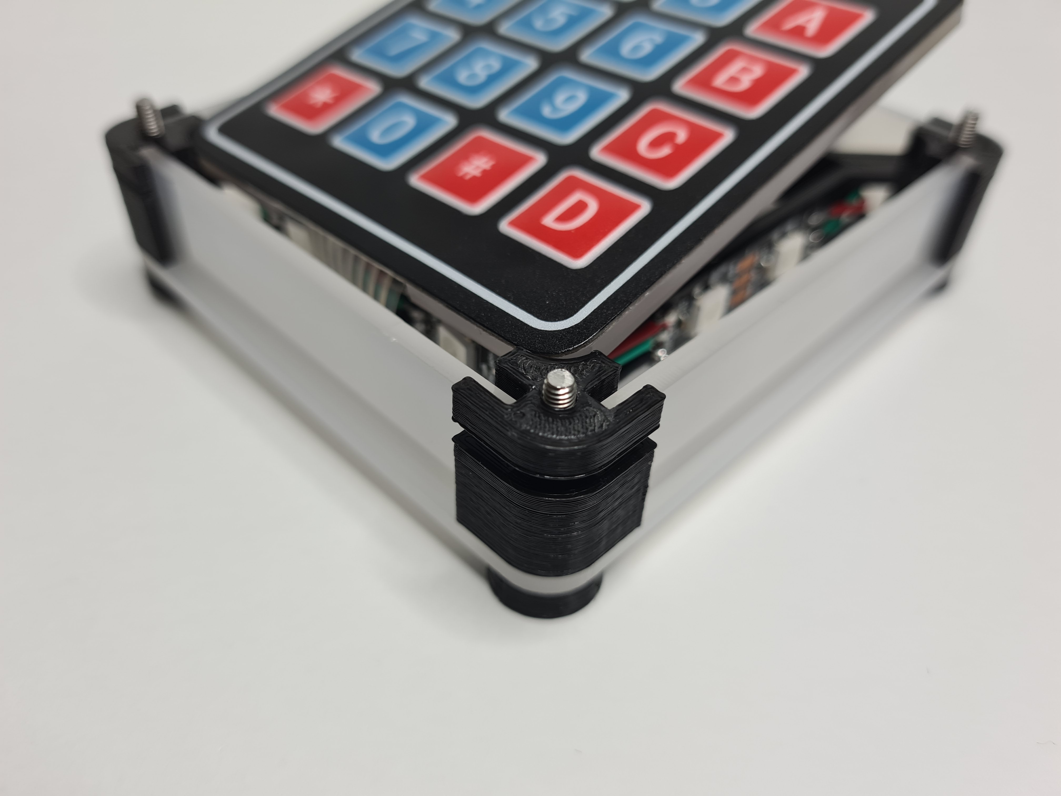
Afterwards was soldering to the neopixel strip. This part should have been easy because the neopixel only needs 3 pins to connect (Data in, 5V and GND). However, because I want to space out the individual LEDs apart, 6 solder joints ended up becoming 24. There are a total of 6 LEDs, split into 2-1-1-2, wrapping around the center part of the corner 3D print, pictured below.
Due to the large amount of connections, I had a lot of practice soldering. Because I did not get the lengths right, I had to desolder and resolder about 12 more times, which gave me even more practice. This surely has given me a lot of experience soldering, although in the future I hope to get it right on the first try.
After soldering to the board, the electronics has been completed.
Electronics Test
Once I got the solder done, I tested the connections using the examples in arduino to see if they still work. I used the built in strandtest from the Adafruit library to test the neopixel strips and used the code for a 4x4 keypad from [here]. From the tests, the all the solder joints work with no issues, meaning I can continue with the code in week 3.
Week 3
Now that I have finished the case and the electronics, this week I plan to finish the code and final integration.
The Code
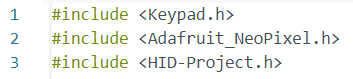
The full ino file can be found at the top of this page. In this section I will only be explaining the main parts of the code and how I got the code. For this project, 3 arduino libraries were needed. These libraries are arduino's built in Keypad.h, Adafruit_Neopixel.h by Adafruit and HID-Project.h by Nicohood.
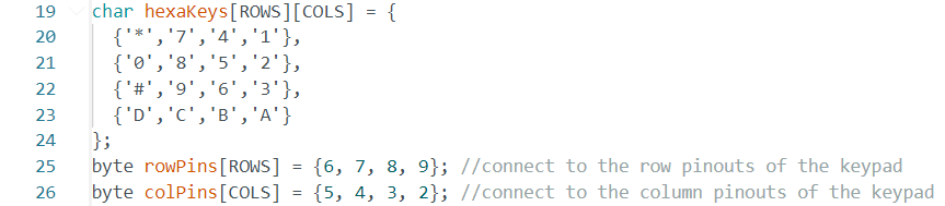
First, I used the keypad code from the test example and modified it so that the keypad pattern better reflected what the buttons are supposed to be. When I soldered it, the connections were fine but I messed up the rows and columns of the keypad. Instead of resoldering I decided to fix it in code here.
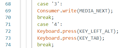
In essence, the main bulk of the code is a large switch case, with each case corresponding to a button on the keypad and doing something different. For example, below is a part of the 16 cases long switch case. When button '3' is pressed on the keypad, the program recognises it as case 3 and execute the commands for case 3, which is to tell the computer to go to the next media. If button '4' is pressed instead, it will tell the computer to press left alt then tab, switching between open applications.
The binds can be changed anytime by changing the code. In general, numbers and letters are Keyboard.press('_') where _ is the letter or number, modifier keys like left alt are Keyboard.press(KEY_LEFT_ALT), and media keys like pause are Consumer.write(MEDIA_PLAY_PAUSE). The switch case just has to be changed to whatever bind or macro you want to set.
Majority of the cases follow something similar except switch case 'A'. I wanted to make this button cycle through different RGB LED modes, so the switch case is different. I got the code for the RGB lighting by combining the pattern updating, rainbow and rainbowCycle code from a comment by "Grumpy Mike" on an arduino forum [here] and the code for solid colors from an arduino project by Arnov Sharma [here].
How the color switching works is that first the arduino detects if 'A' has been pressed. Once it has, it will add 1 to the pattern number.
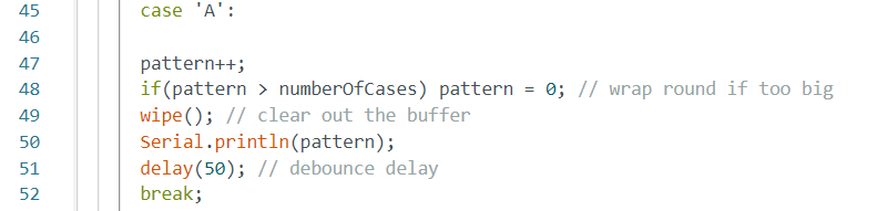
At the same time, a function to keep updating the pattern is repeated indefinitely. Although this does not really affect the solid color options, for the last 2 options, rainbow and rainbowCycle, it is very important for the pattern to repeatedly update.

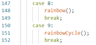
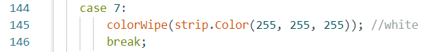
The function is its own switch case, depending on the pattern number dictated by the 'A' button. The switch cases range from off to solid colors,
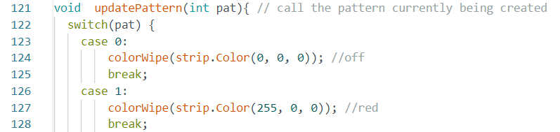
to the rainbow and rainbowCycle cases. Currently there is an off state, 7 solid color states and 2 dynamic color states.
Modifying the code.
The binds can be changed anytime by changing the code. In general, numbers and letters are Keyboard.press('_') where _ is the letter or number, modifier keys like left alt are Keyboard.press(KEY_LEFT_ALT), and media keys like pause are Consumer.write(MEDIA_PLAY_PAUSE). The switch case just has to be changed to whatever bind or macro you want to set.
To add more solid color modes to the RGB, first the intervals in line 9 need to be updated. The position of the number corresponds to the switch case the interval is for. Currently I have the interval for solid colors as '20' and the intervals for rainbow and rainbowCycle as '50'. If more colors and modes are added, this line will need to be updated to reflect the change.

Then the number of cases in line 11 need to be changed

Finally, just add another case to the switch case. The color is determined by the 3 numbers in the strip.Colour brackets. Each number corresponds to a value of RED, GREEN and BLUE respectively, ranging from 0 to 255.
Testing the Code
Below is a video test of some of the functions of the keypad. Although not all the macros are shown, the other parts of the code still work as intended.
Final Assembly
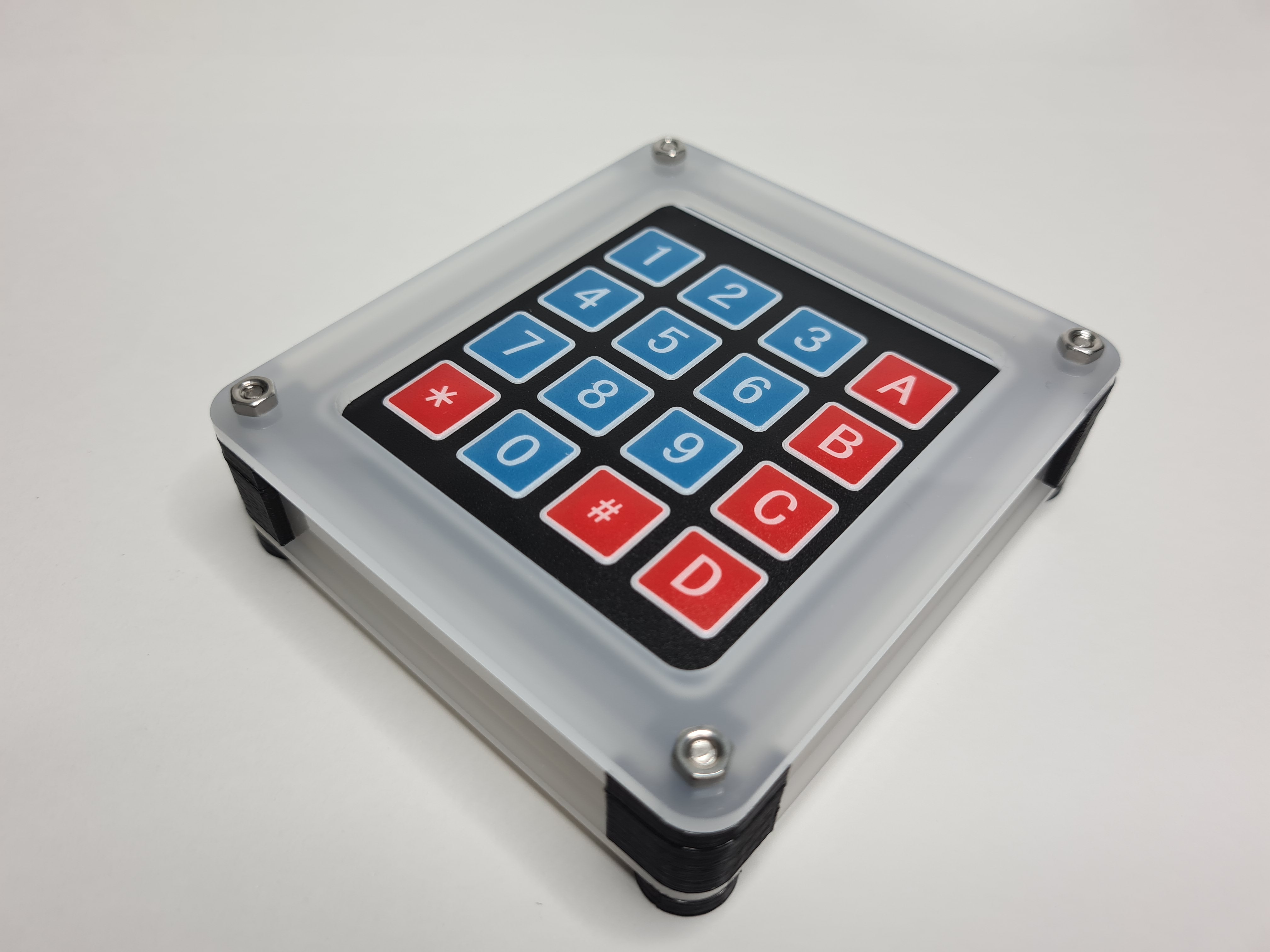
Project Video